

The project has been submitted to eVolo Skyscrapper Competition 2024, with three main concepts and various calculations for it. I've been conceptualizing and sketching for this entire project since May 2023, Hope you enjoy it.
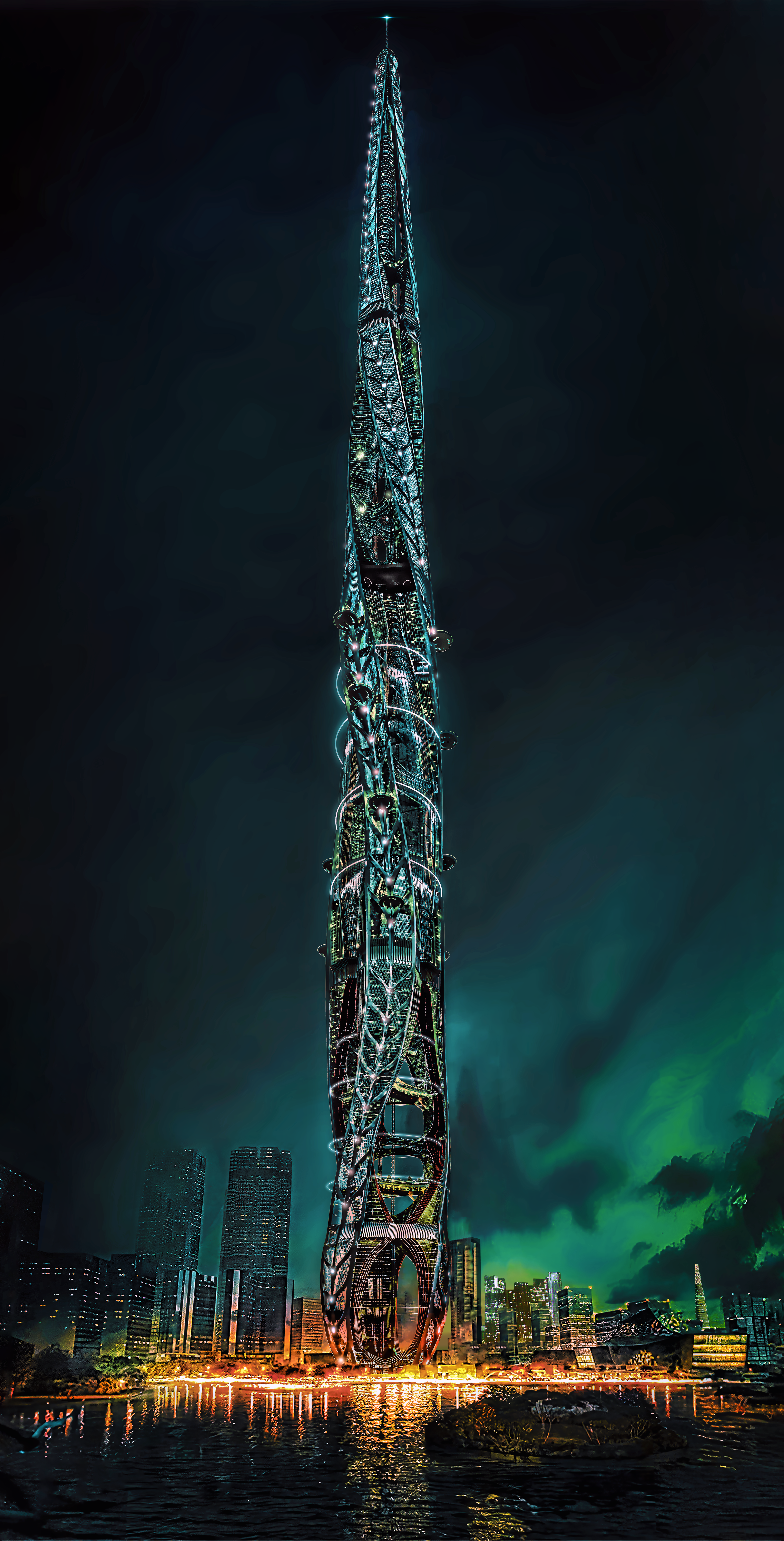
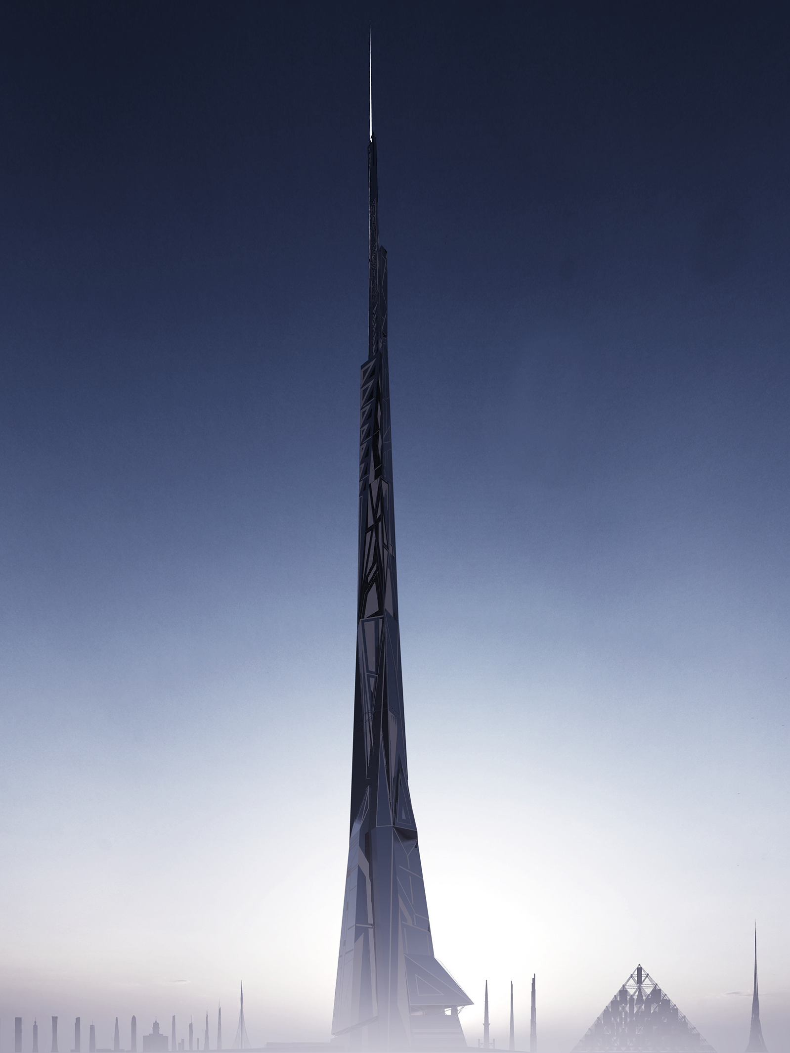
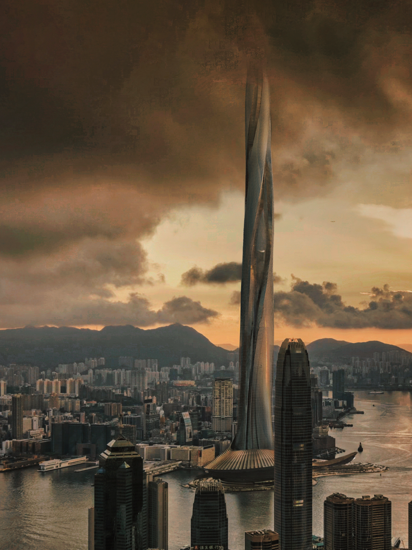
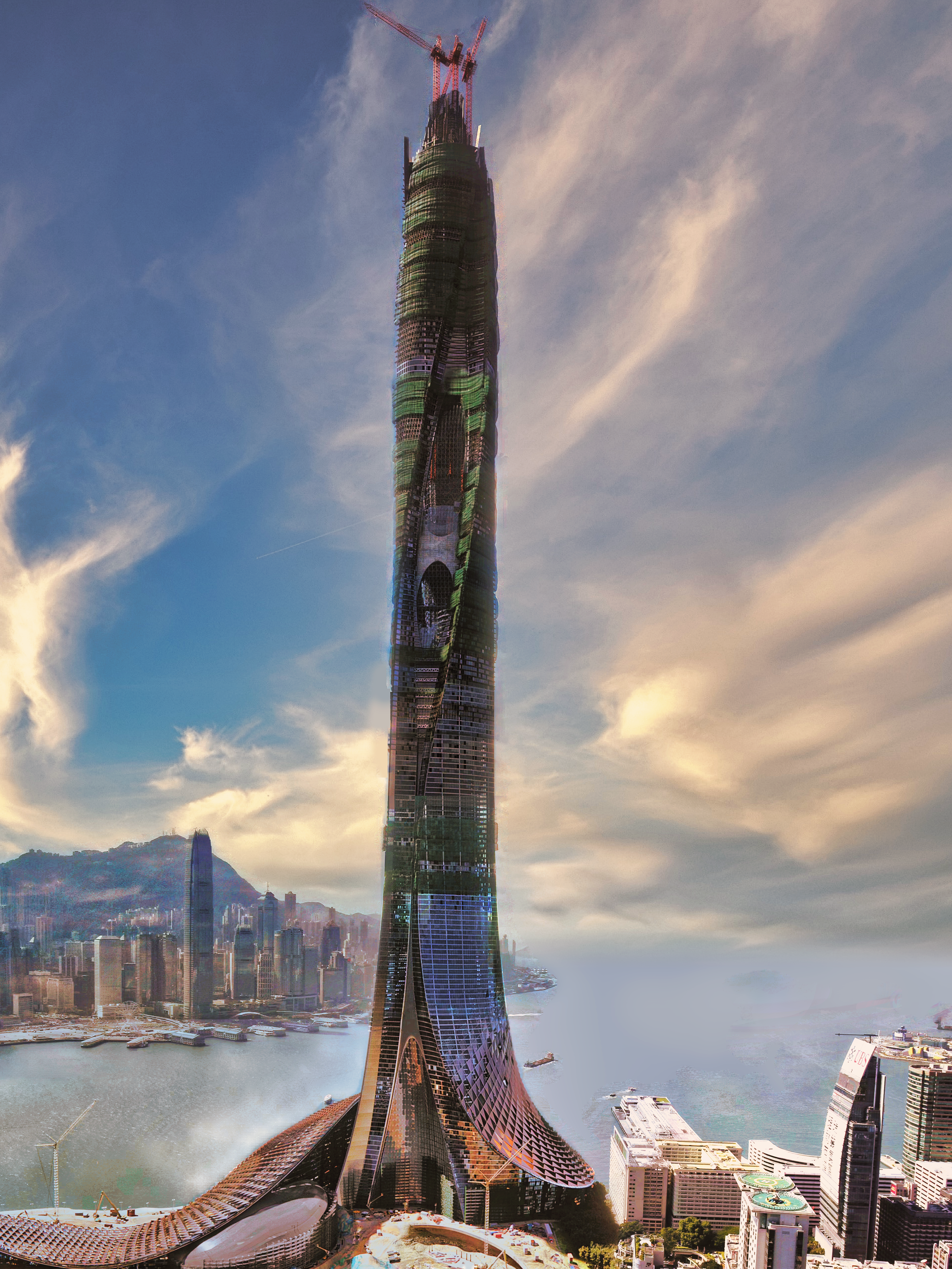
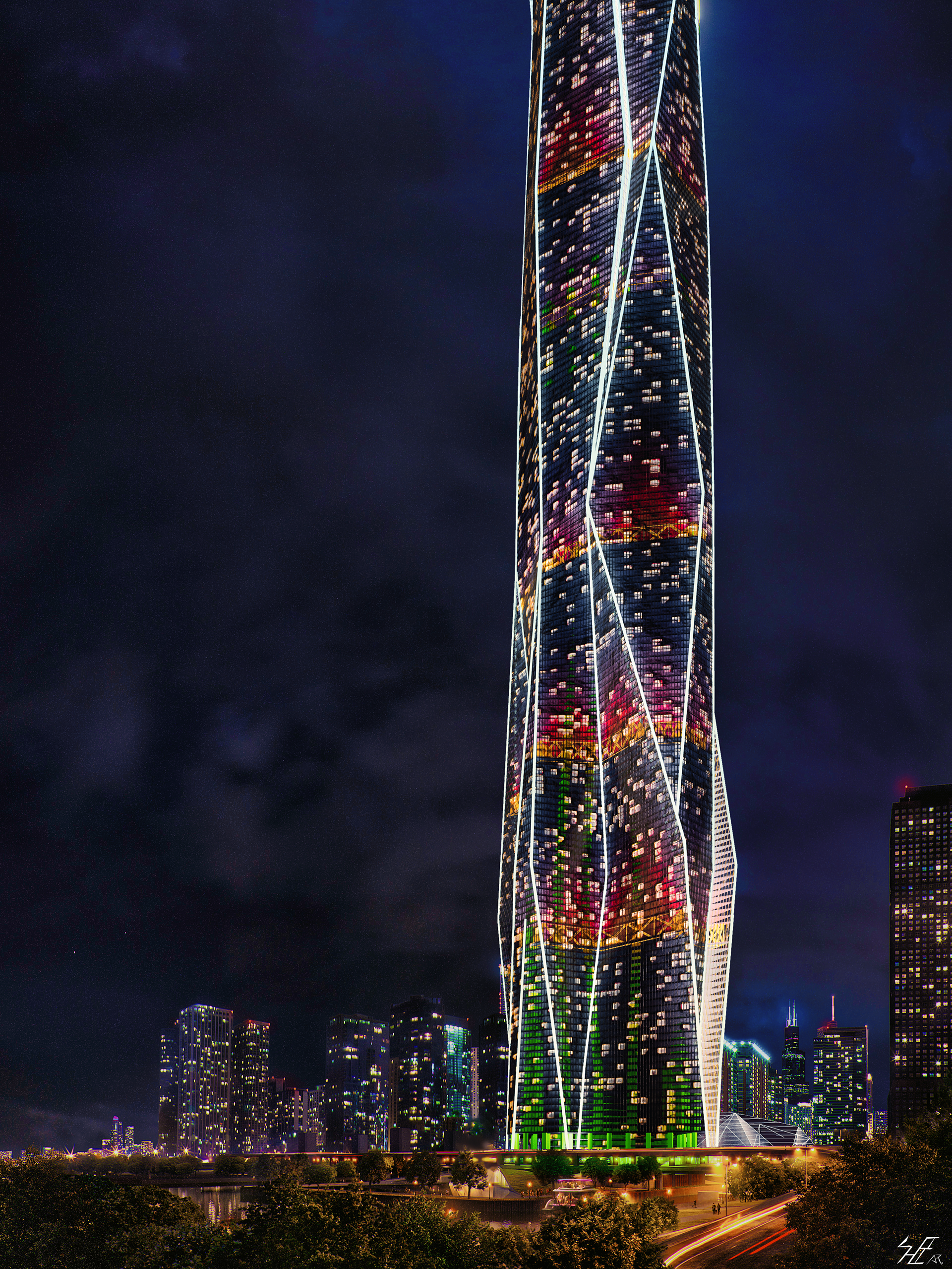
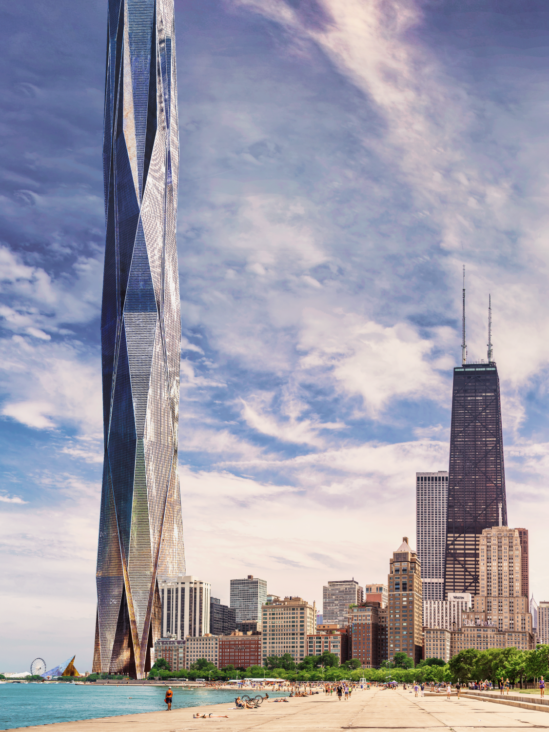
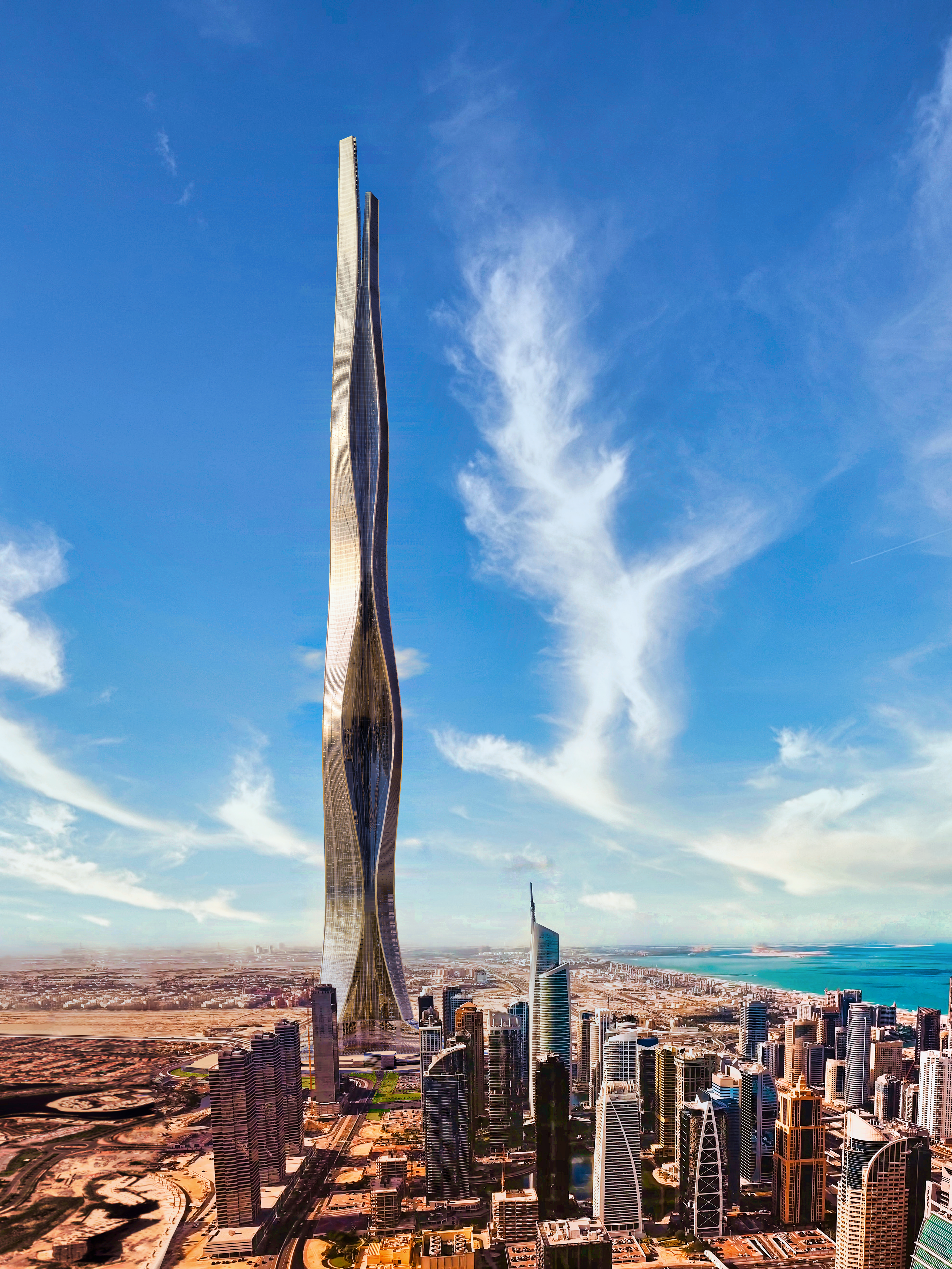
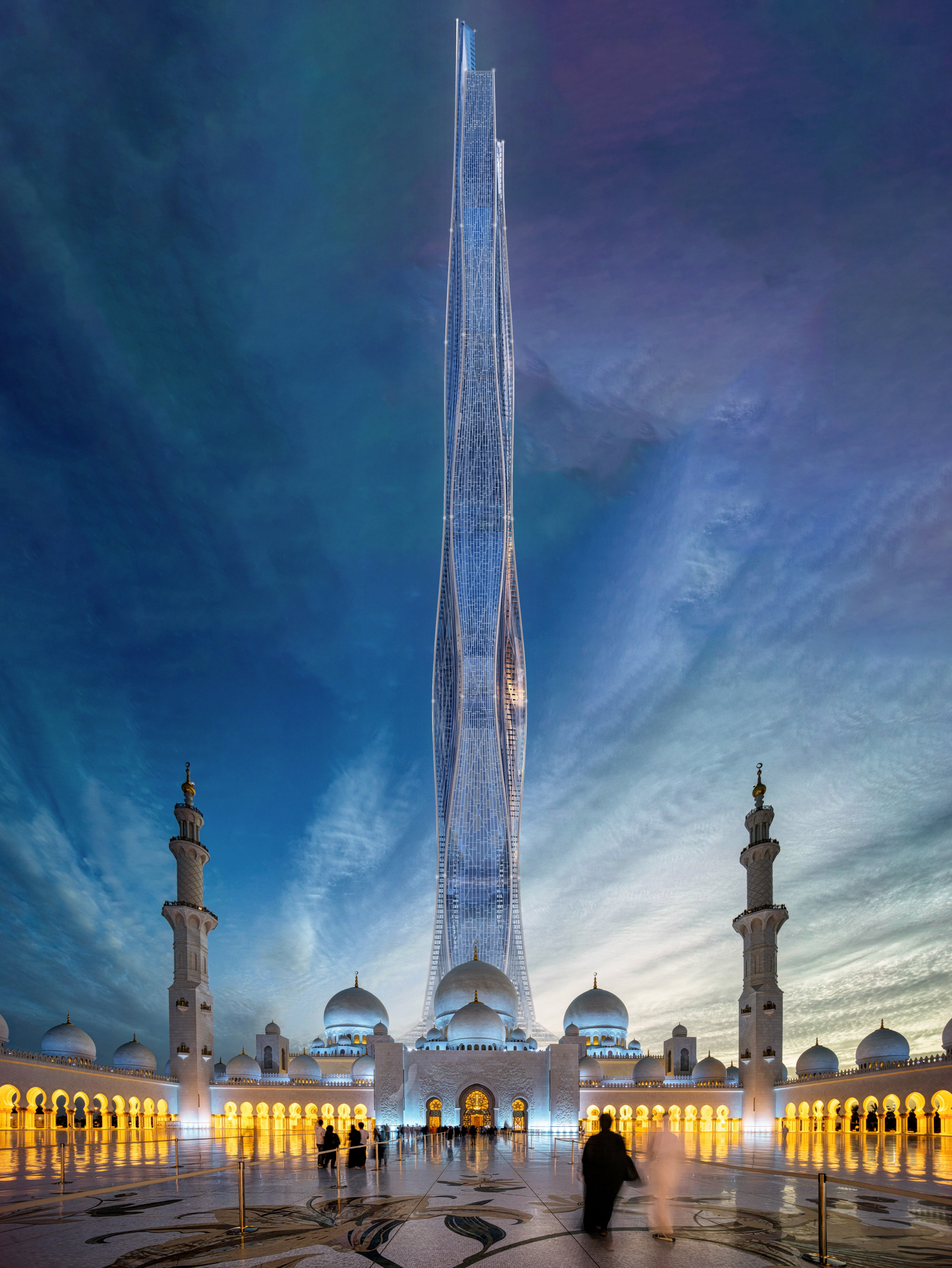
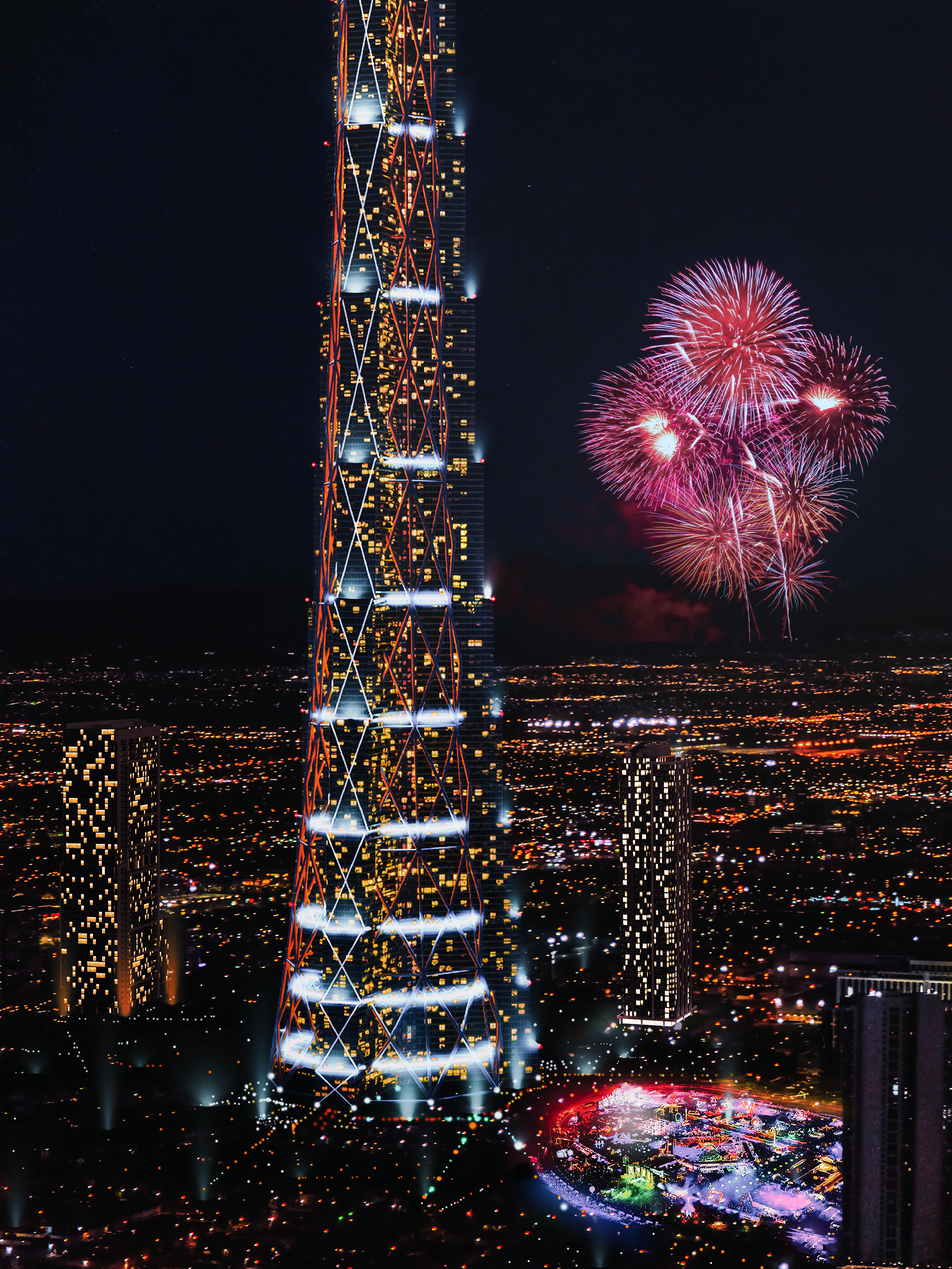
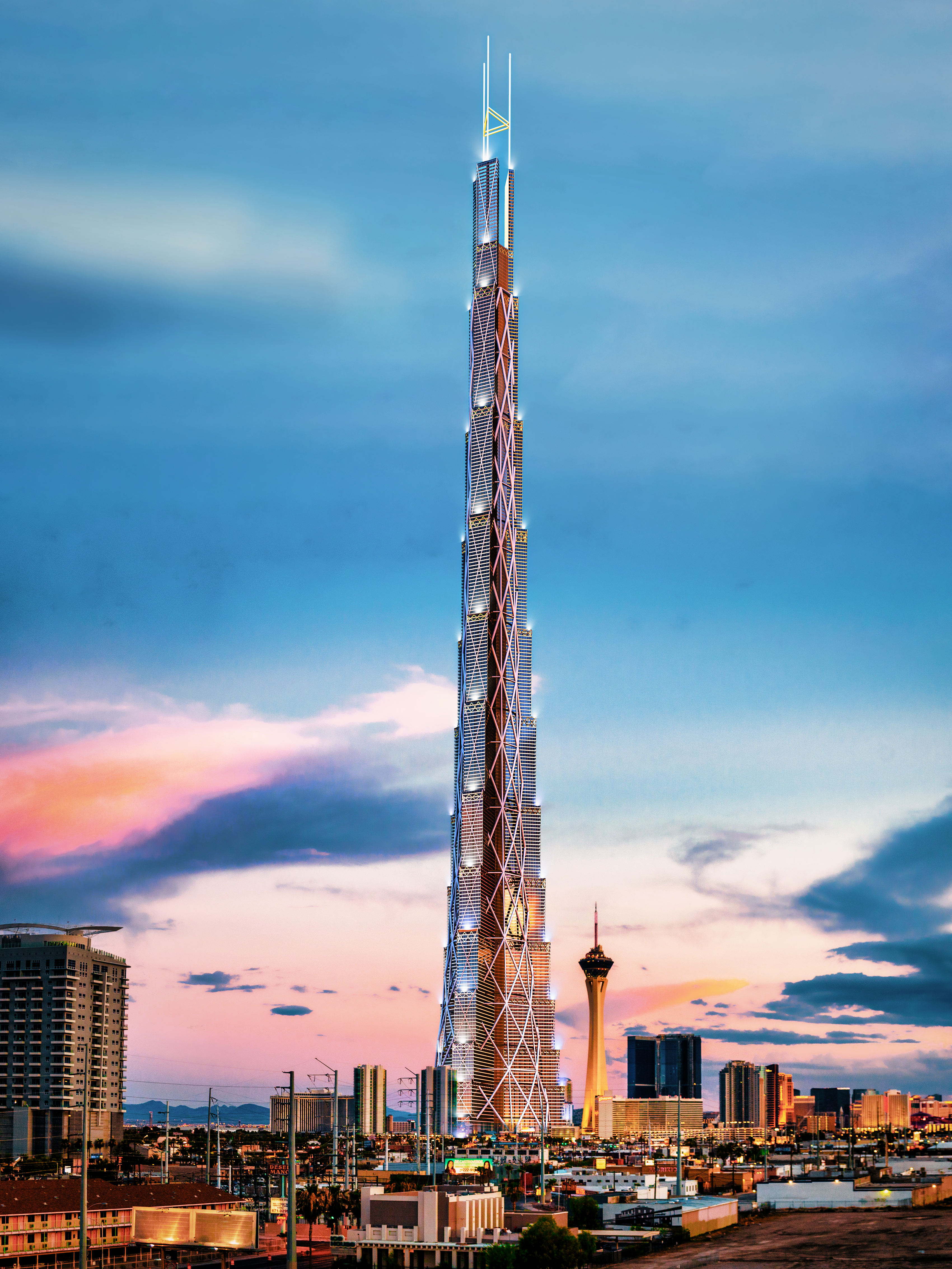
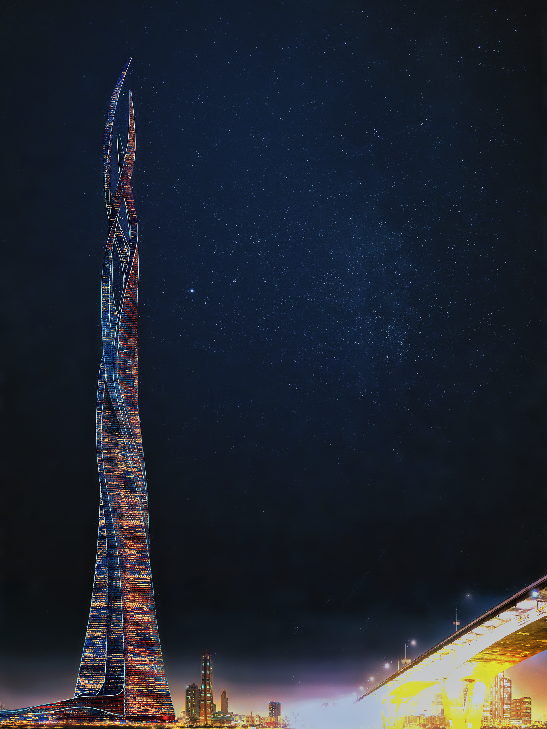
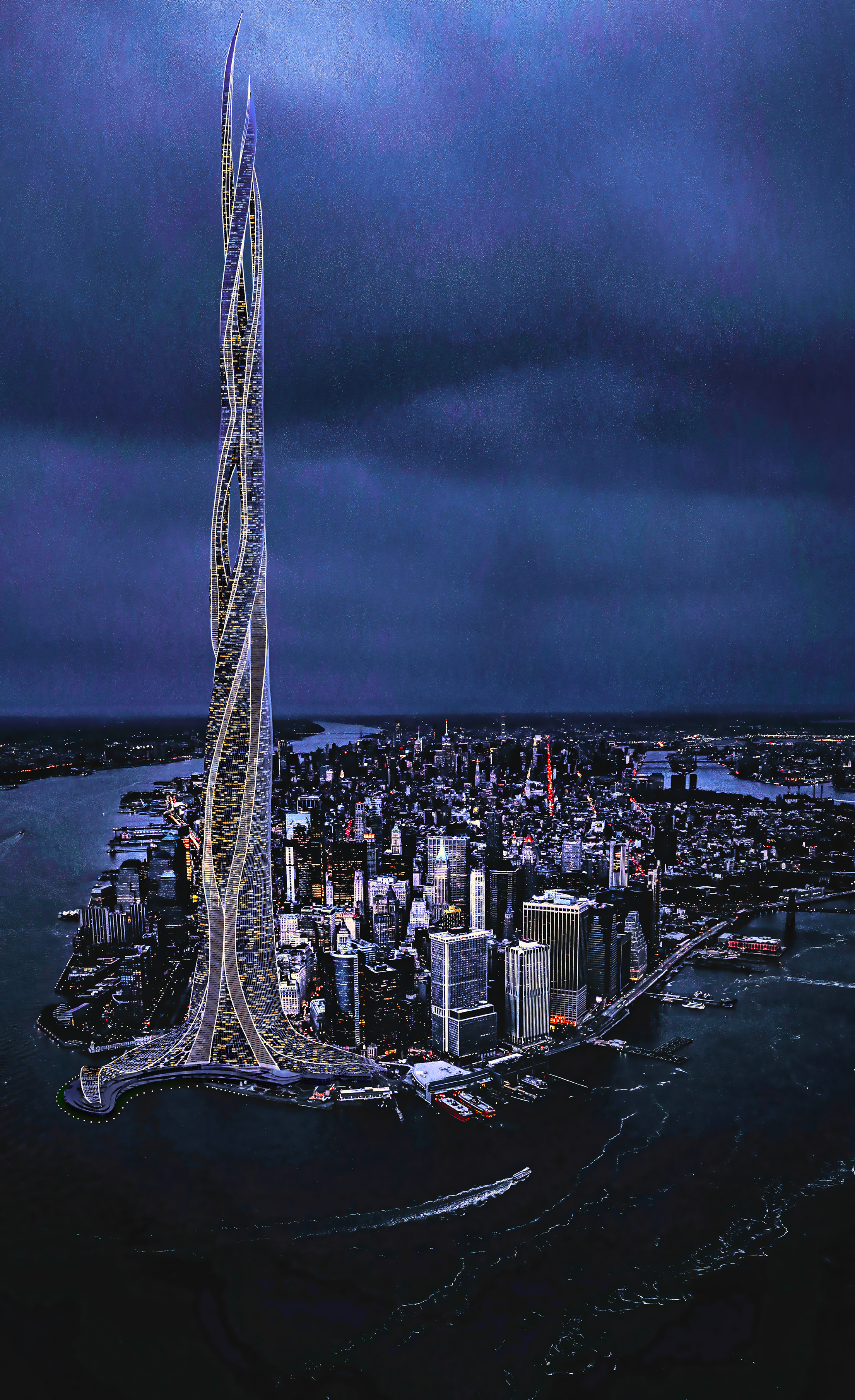
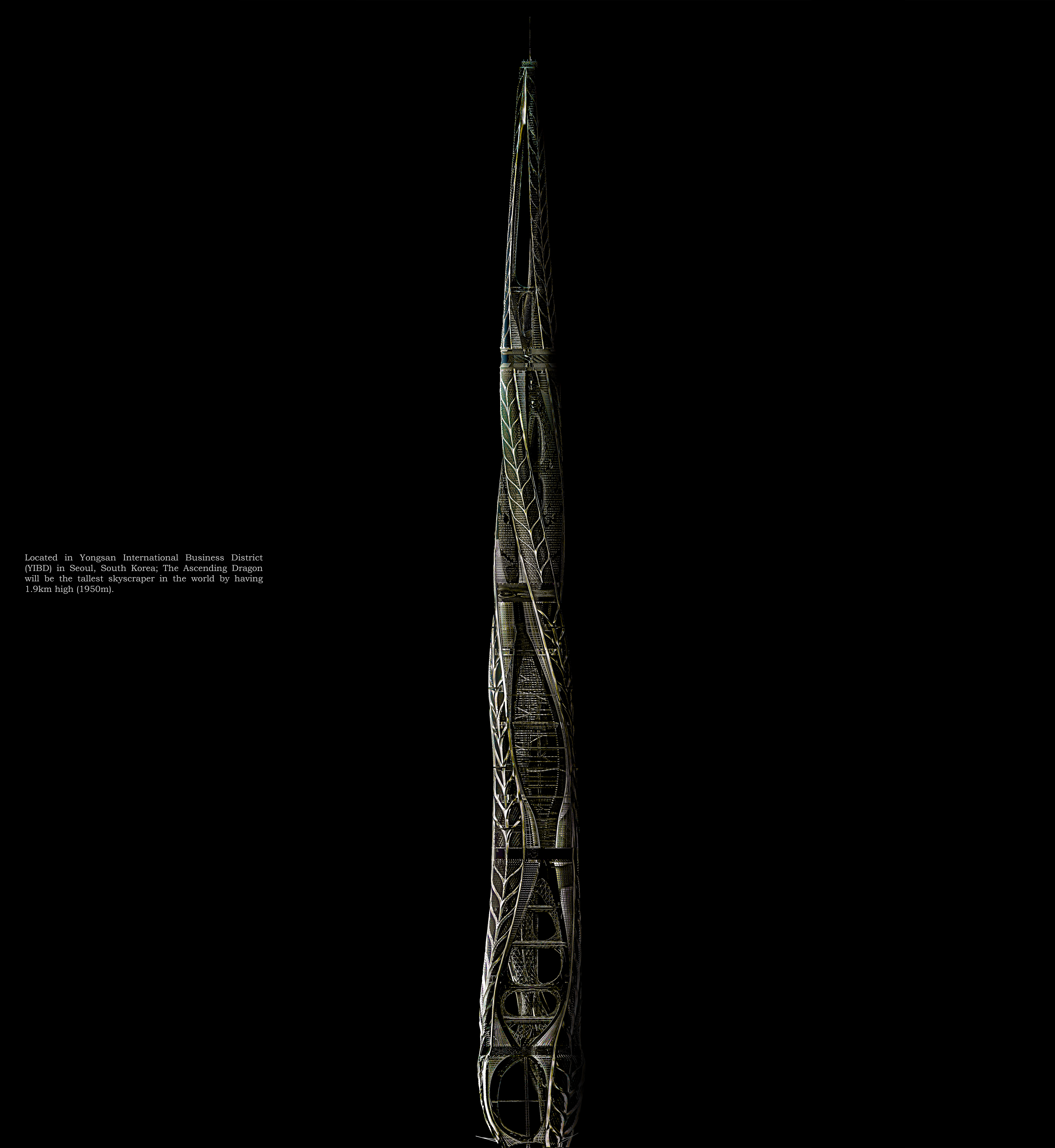
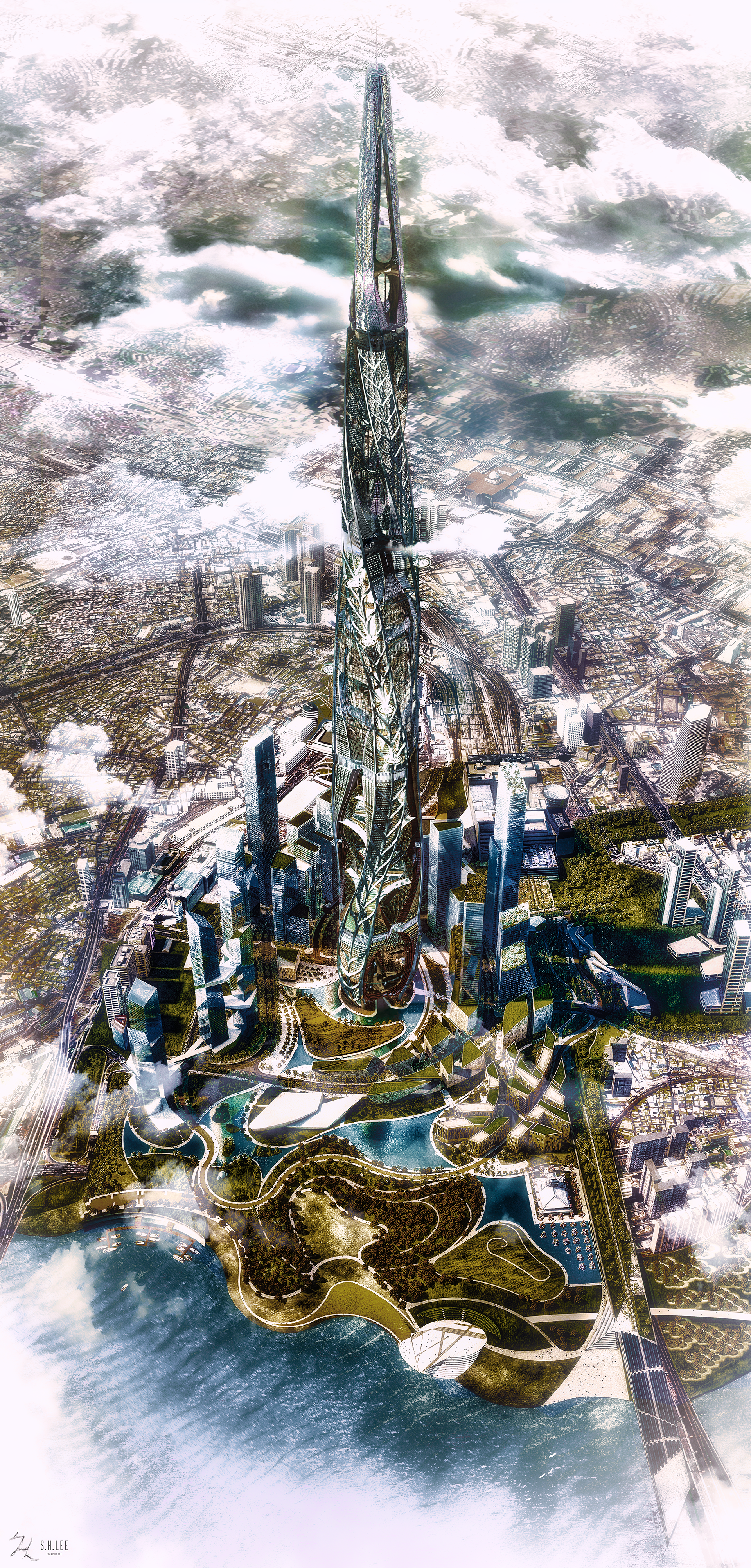
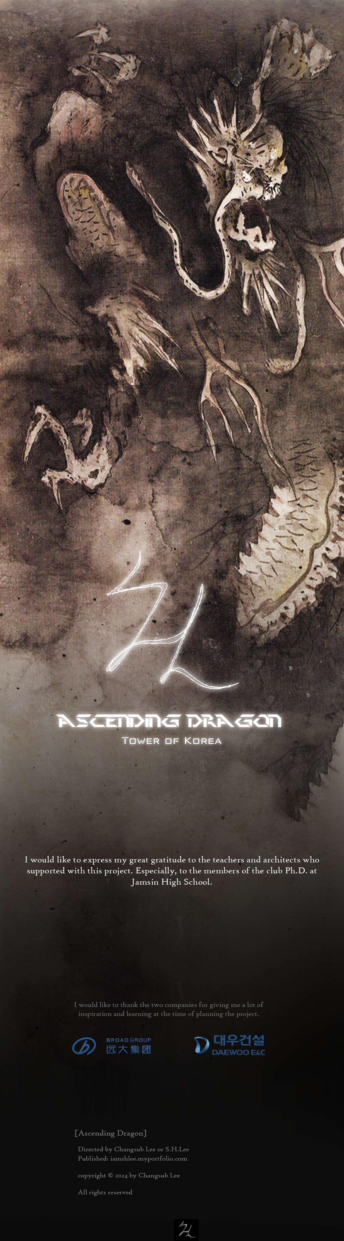
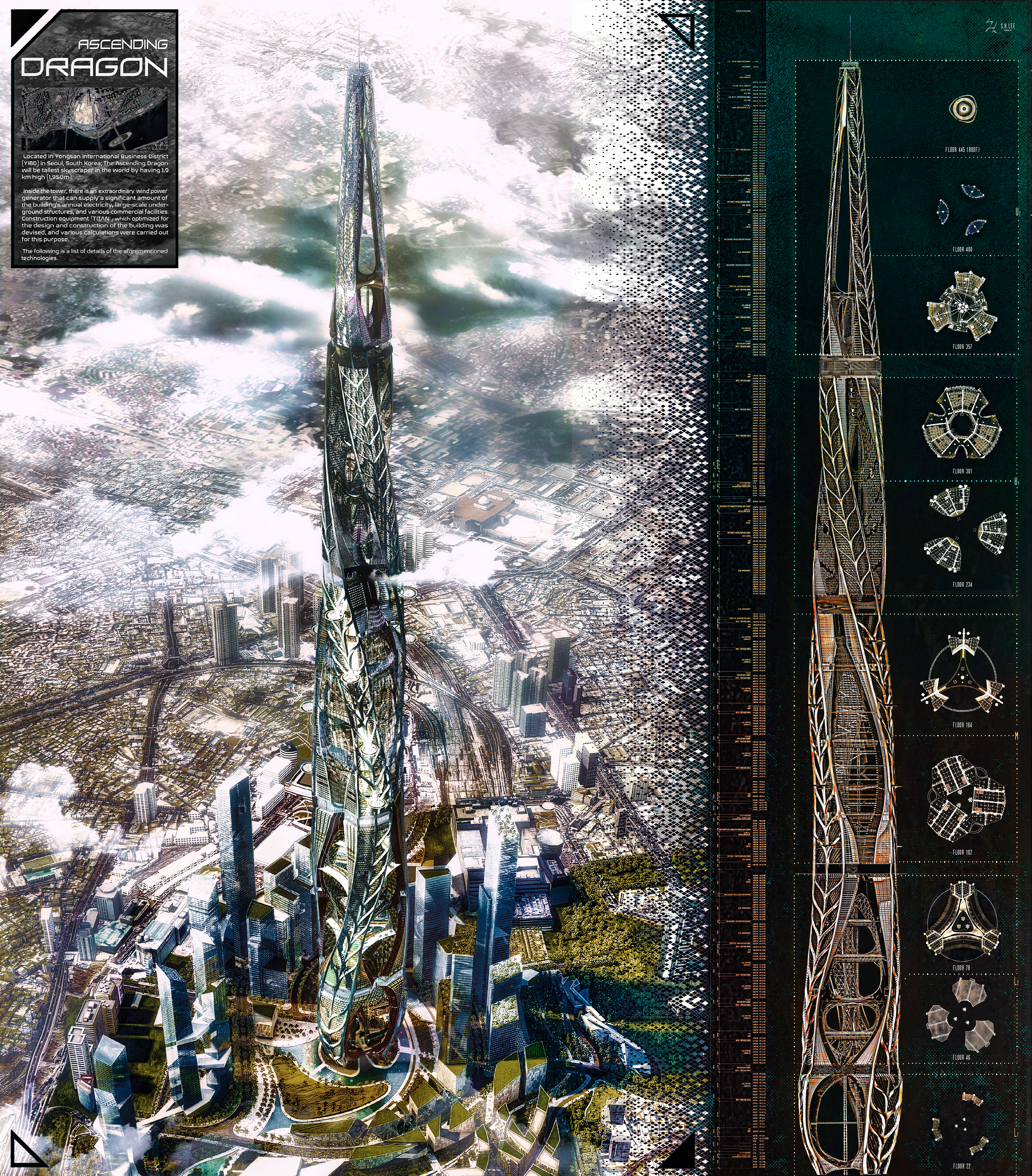
ASCENDING DRAGON

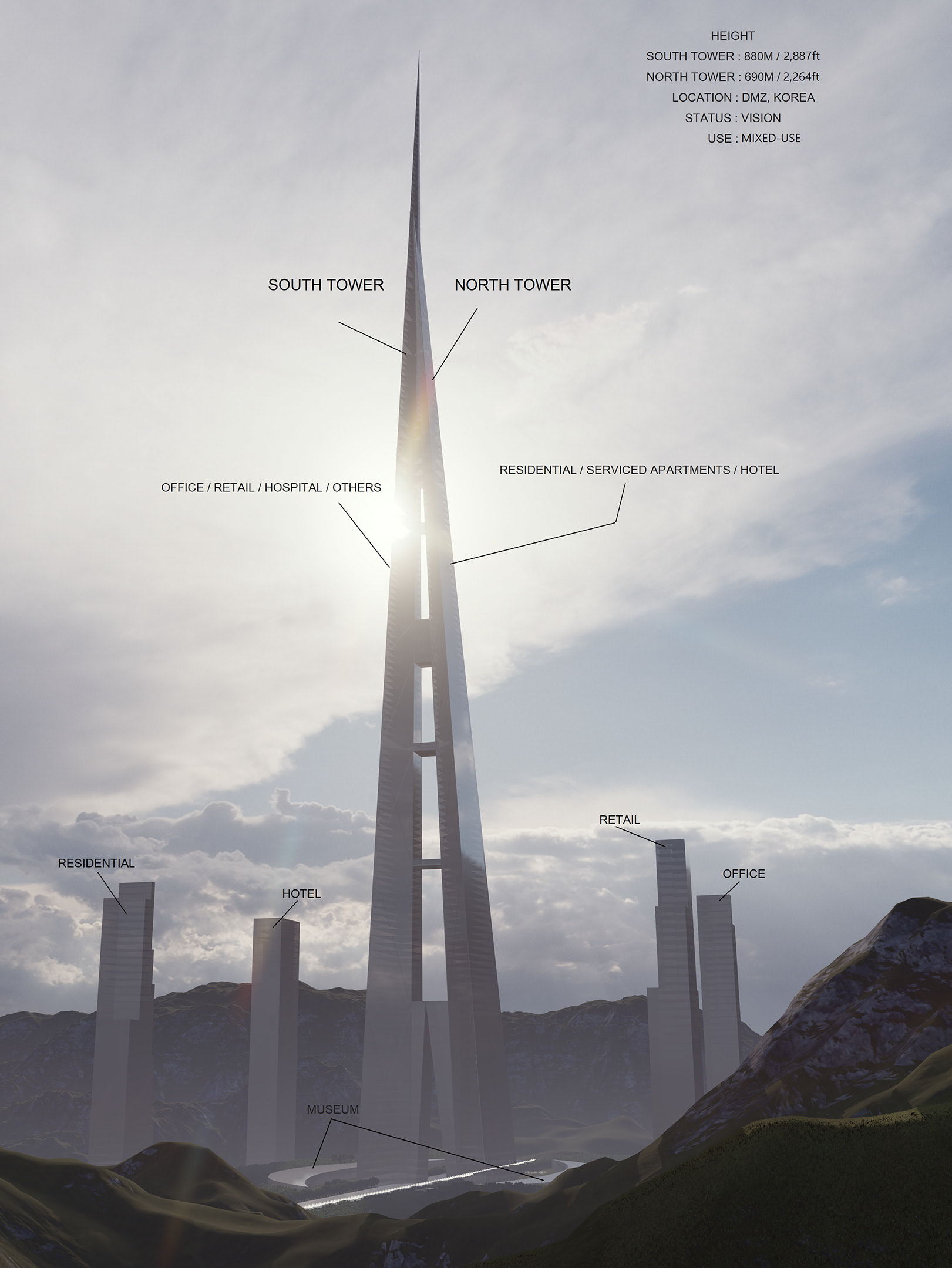
First Board - Overview
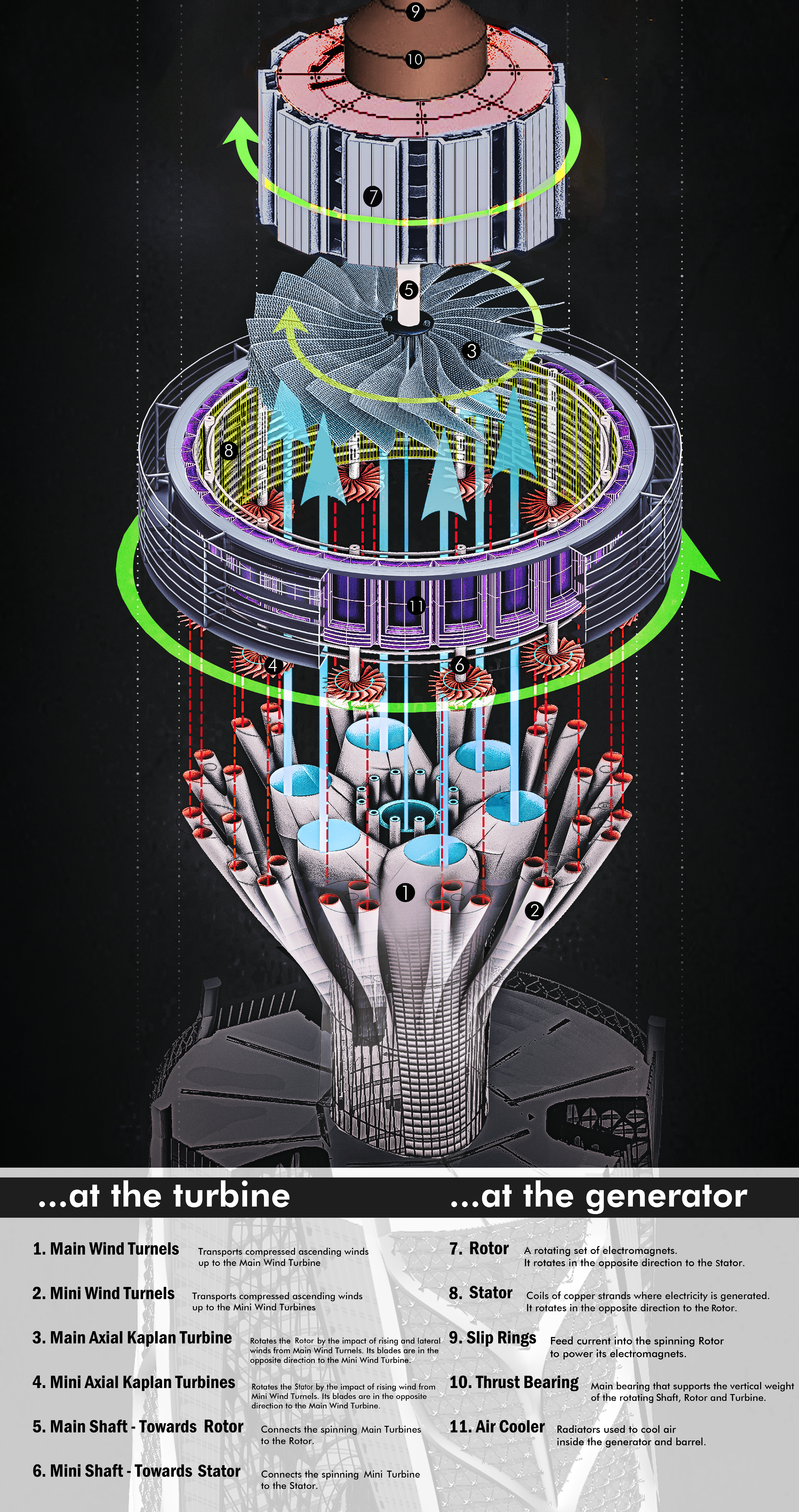
First Board - Power Generation
Second Board - ROOT
Second Board - TITAN
0205-Calculation of: (Turbo Fan / Rotor / Stator's rpm, Convection & Buoyancy, ROOT)
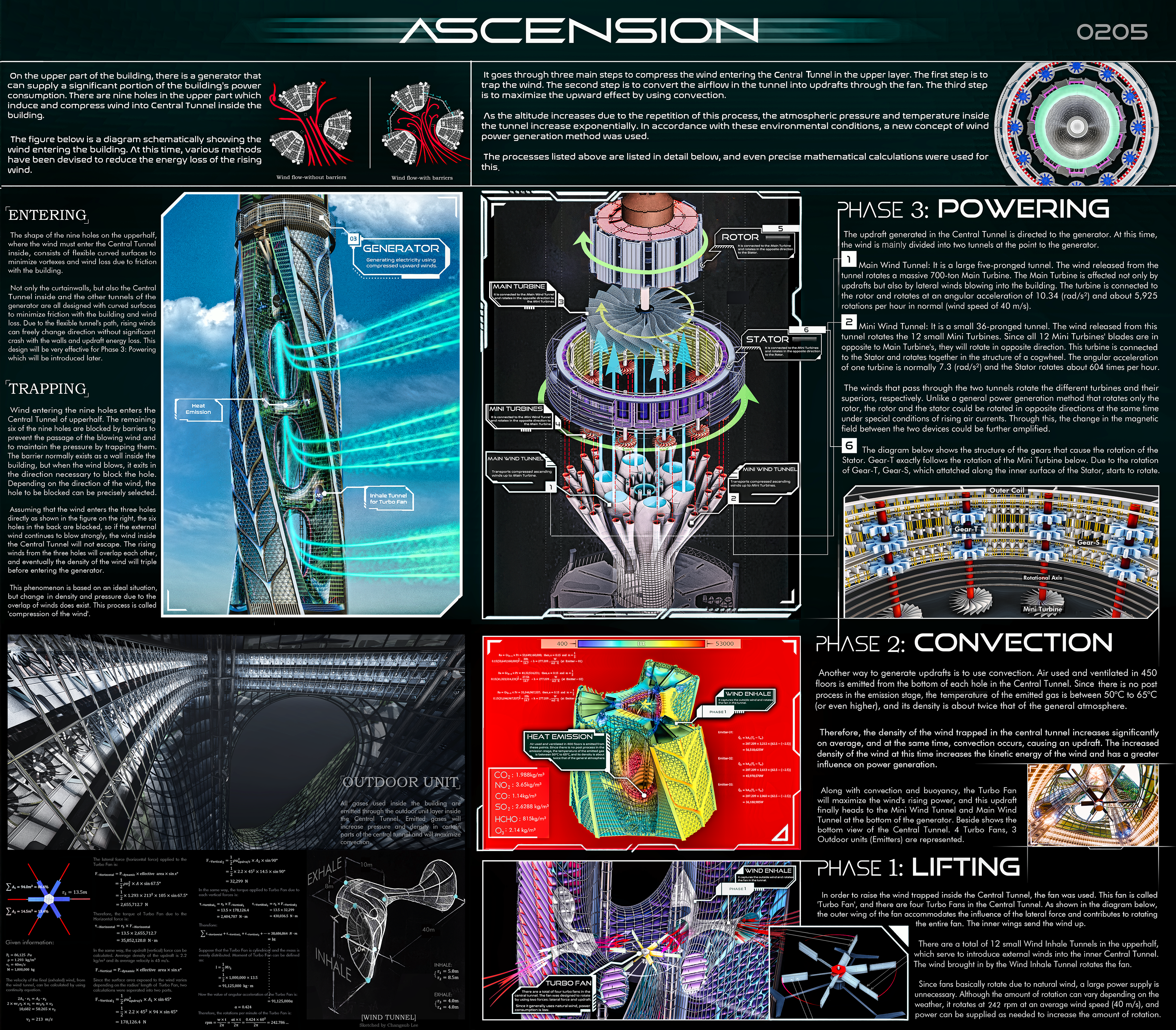
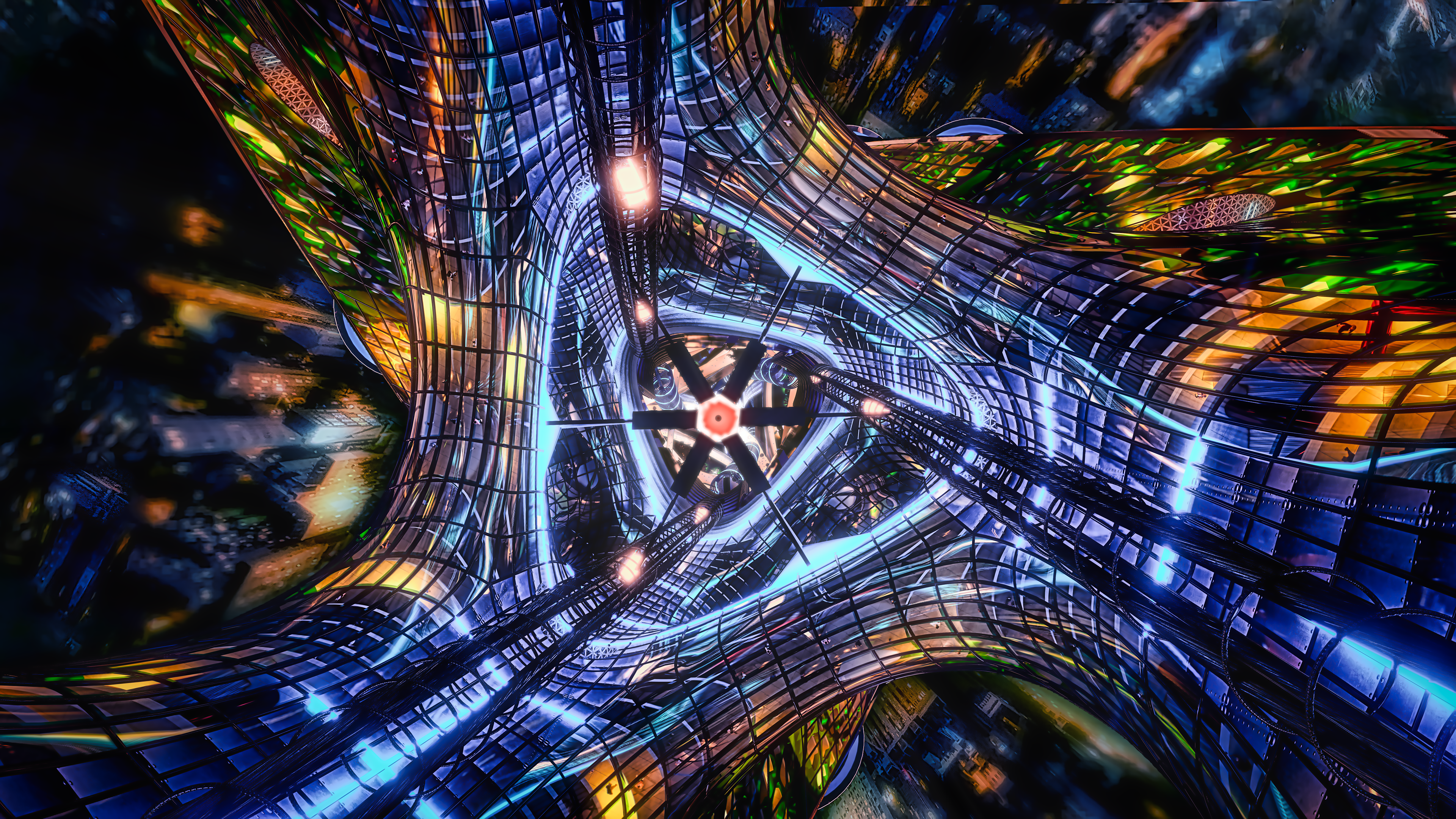
[ENTERING]
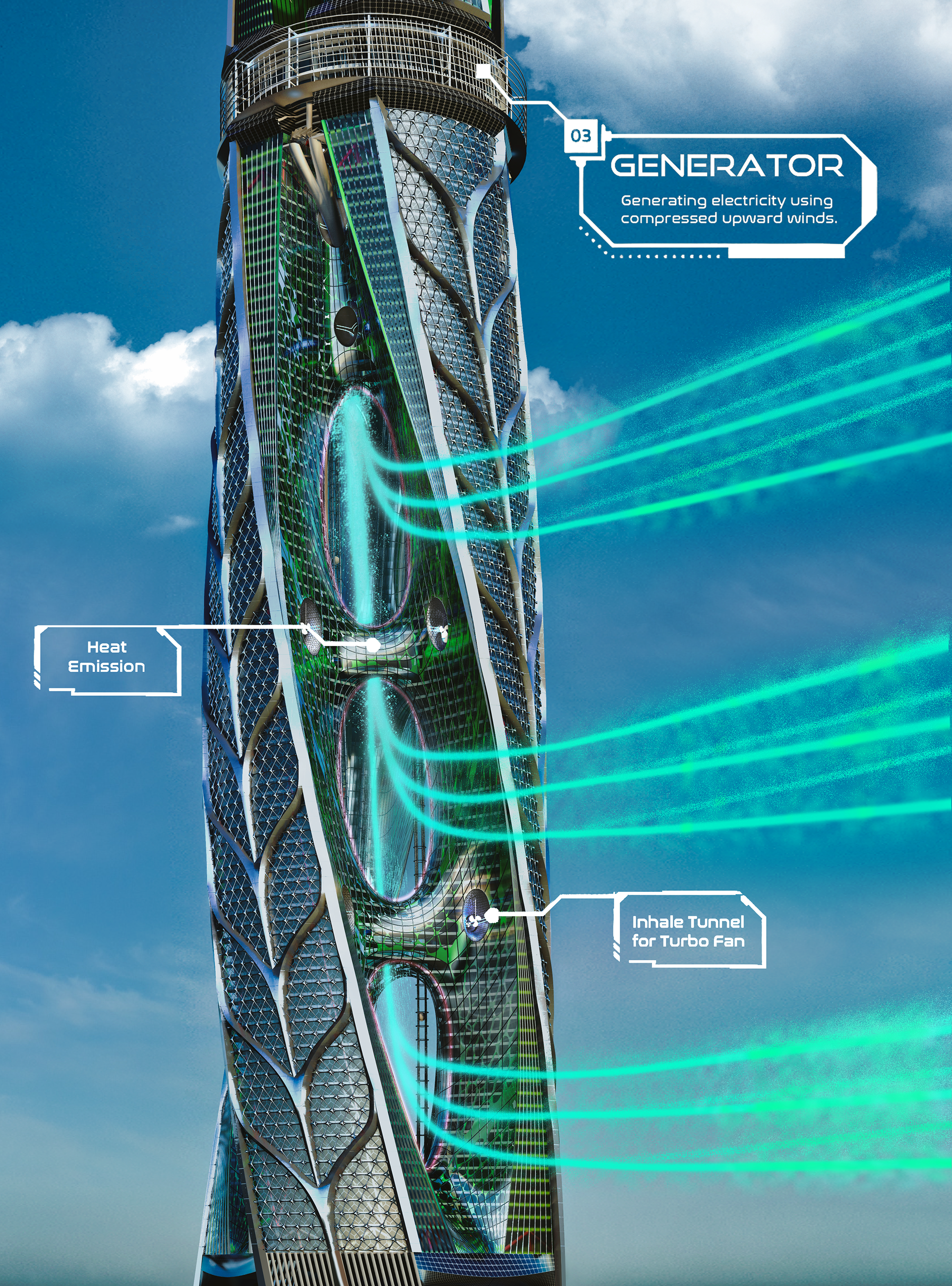
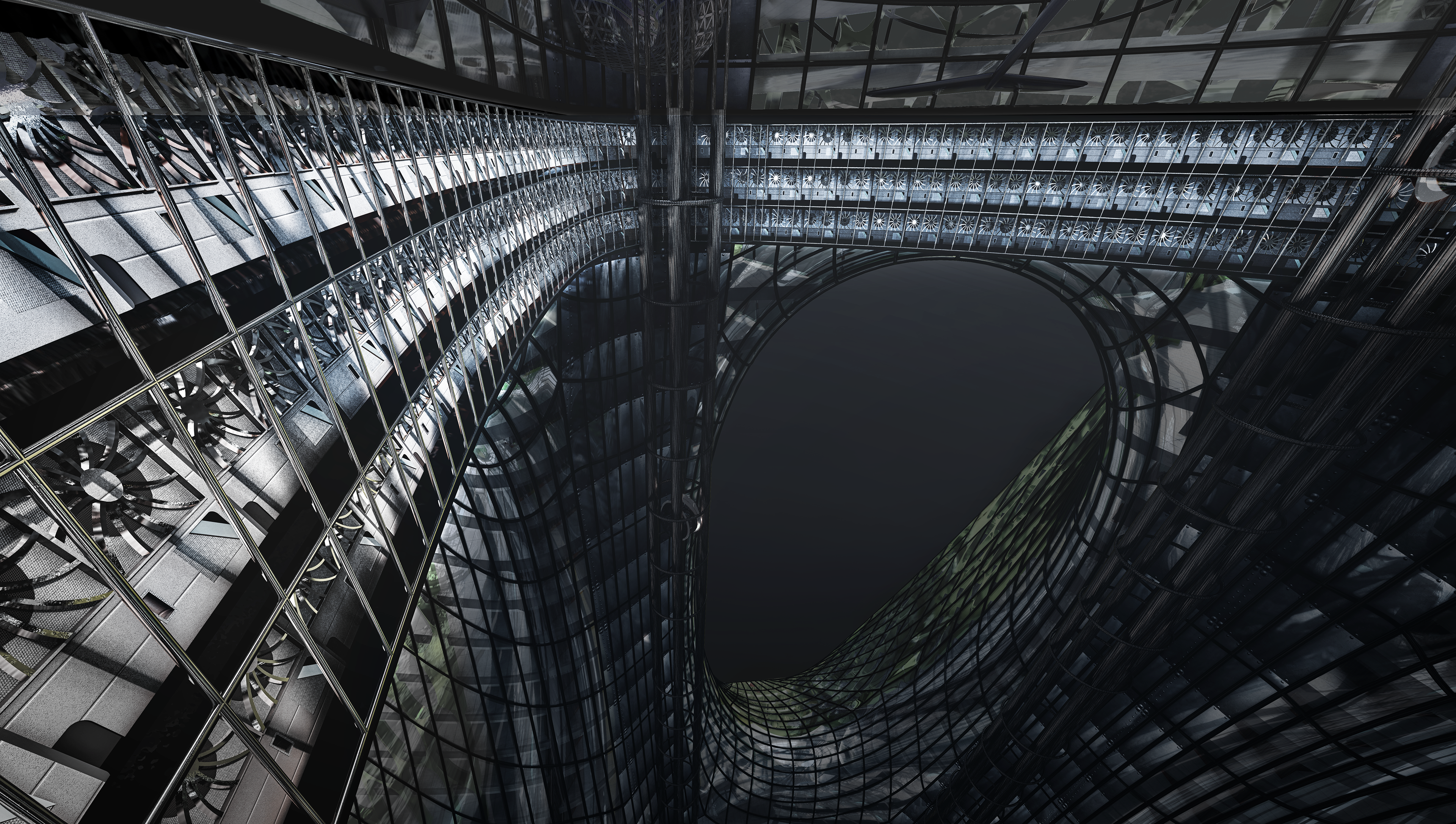
The shape of the nine holes on the upperhalf, where the wind must enter the Central Tunnel inside, consists of flexible curved surfaces to minimize vortexes and wind loss due to friction with the building.
Not only the curtainwalls, but also the Central Tunnel inside and the other tunnels of the generator are all designed with curved surfaces to minimize friction with the building and wind loss. Due to the flexible tunnel's path, rising winds can freely change direction without significant crash with the walls and updraft energy loss. This design will be very effective for Phase 3: Powering which will be introduced later.
[TRAPPING]
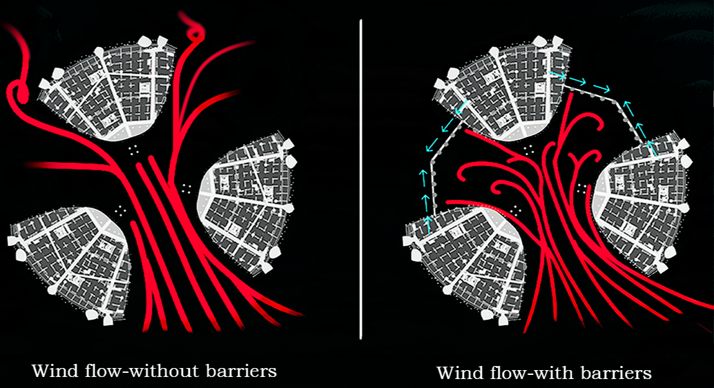
Wind entering the nine holes enters the Central Tunnel of upperhalf. The remaining six of the nine holes are blocked by barriers to prevent the passage of the blowing wind and to maintain the pressure by trapping them. The barrier normally exists as a wall inside the building, but when the wind blows, it exits in the direction necessary to block the hole. Depending on the direction of the wind, the hole to be blocked can be precisely selected.
Assuming that the wind enters the three holes directly as shown in the render on the left, the six holes in the back are blocked, so if the external wind continues to blow strongly, the wind inside the Central Tunnel will not escape. The rising winds from the three holes will overlap each other, and eventually the density of the wind will triple before entering the generator.
This phenomenon is based on an ideal situation, but change in density and pressure due to the overlap of winds does exist. This process is called 'compression of the wind'. The three phases below describe the detailed process of the compression and rise of the wind and the power generator applying them.
Central Tunnel
Phase 1: LIFTING
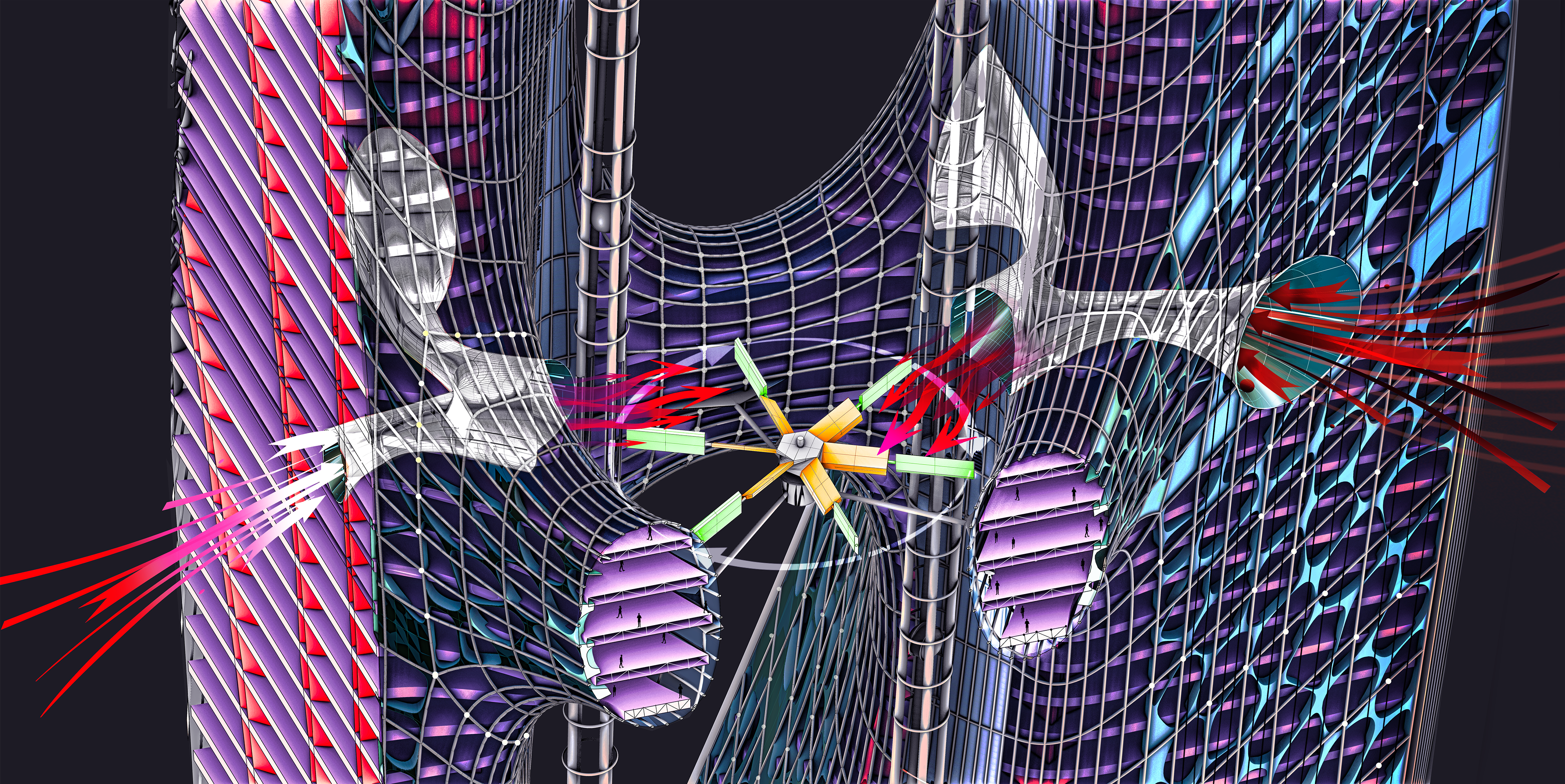
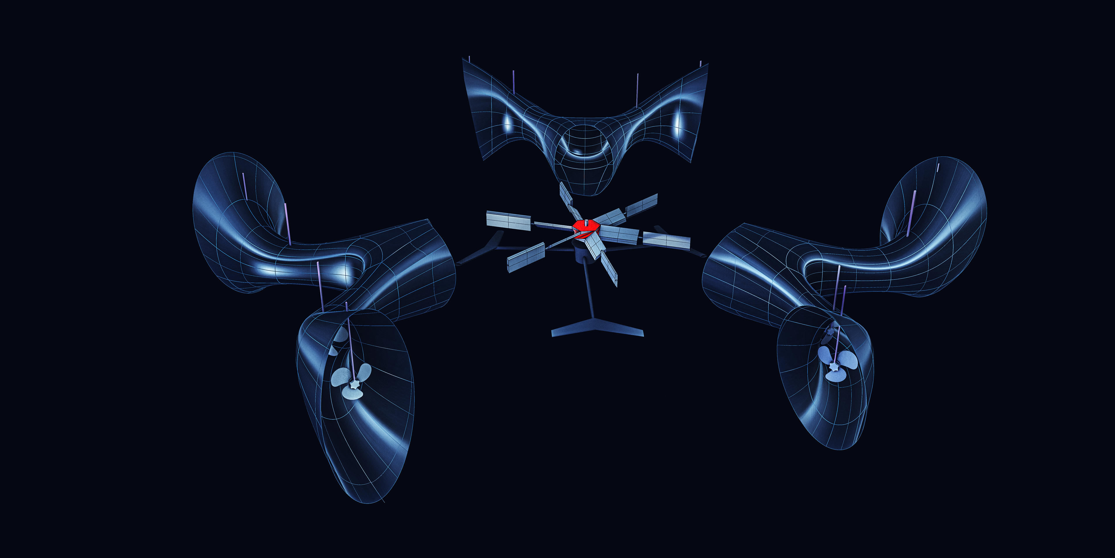
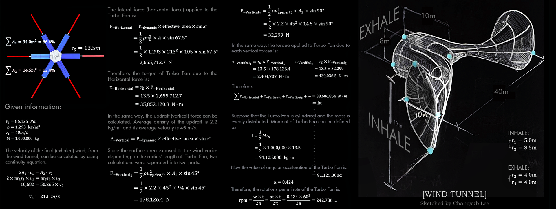
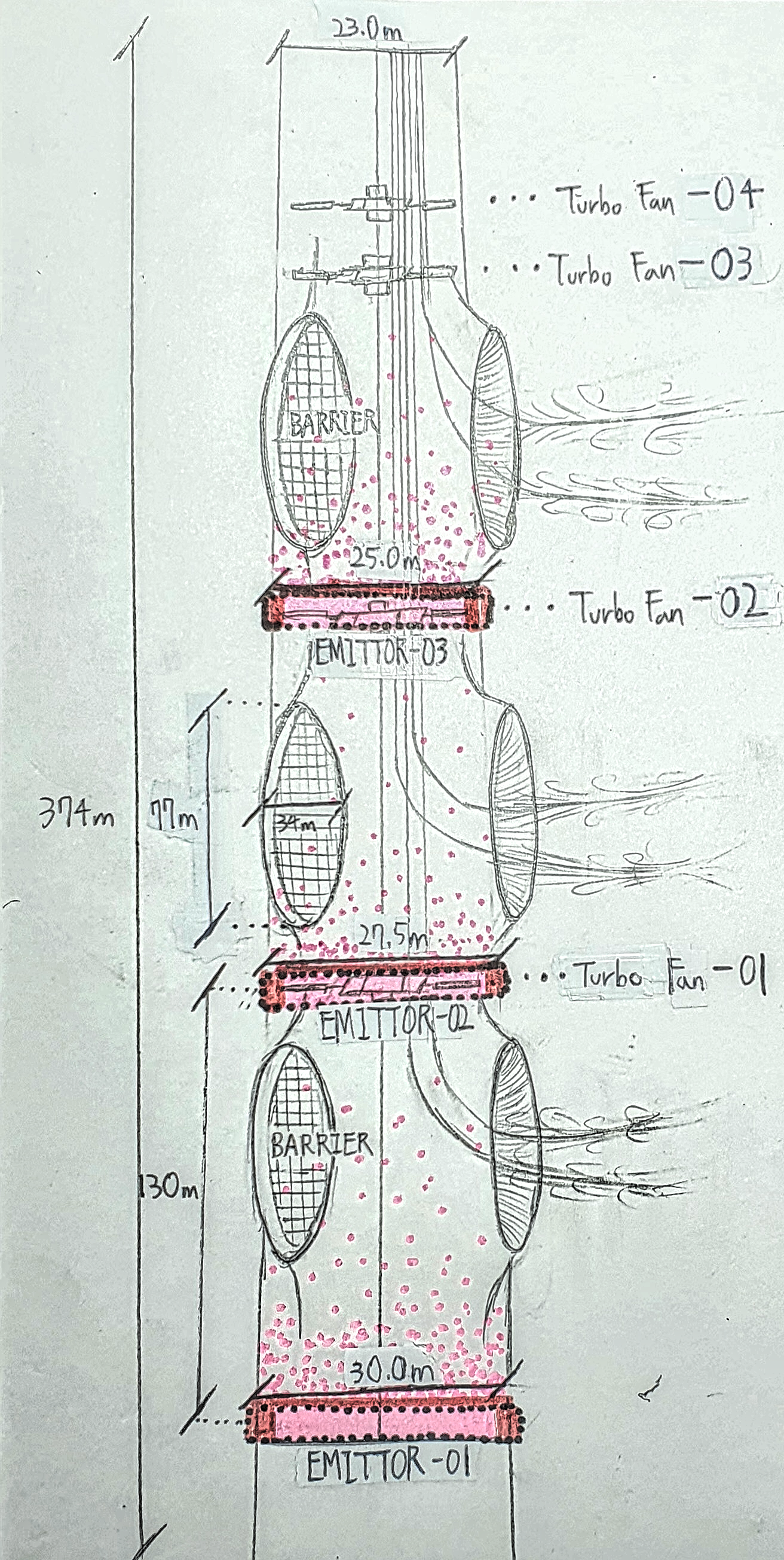
In order to raise the wind trapped inside the Central Tunnel, the fan was used. This can is called 'Turbo Fan', and there are four Turbo Fans in the Central Tunnel. As shown in the diagram below and above, the outer wings of the fan accomodate the influence of the lateral force and contributes to rotating the entire fan. The inner wings send the wind up.
There are a total of 12 small wind passages in the upperhalf, which serve to introduce external winds into the inner Central Tunnel. The wind brought in by this passage rotates the fan.
Since fans basically rotate due to natural wind, a large power supply is unnecessary. Although the amount of rotation can vary depending on the weather, it rotates at 242 rpm at an average wind speed (40m/s), and power can be supplied as needed to increase the amount of rotation.
Phase 2: CONVECTION & BUOYANCY
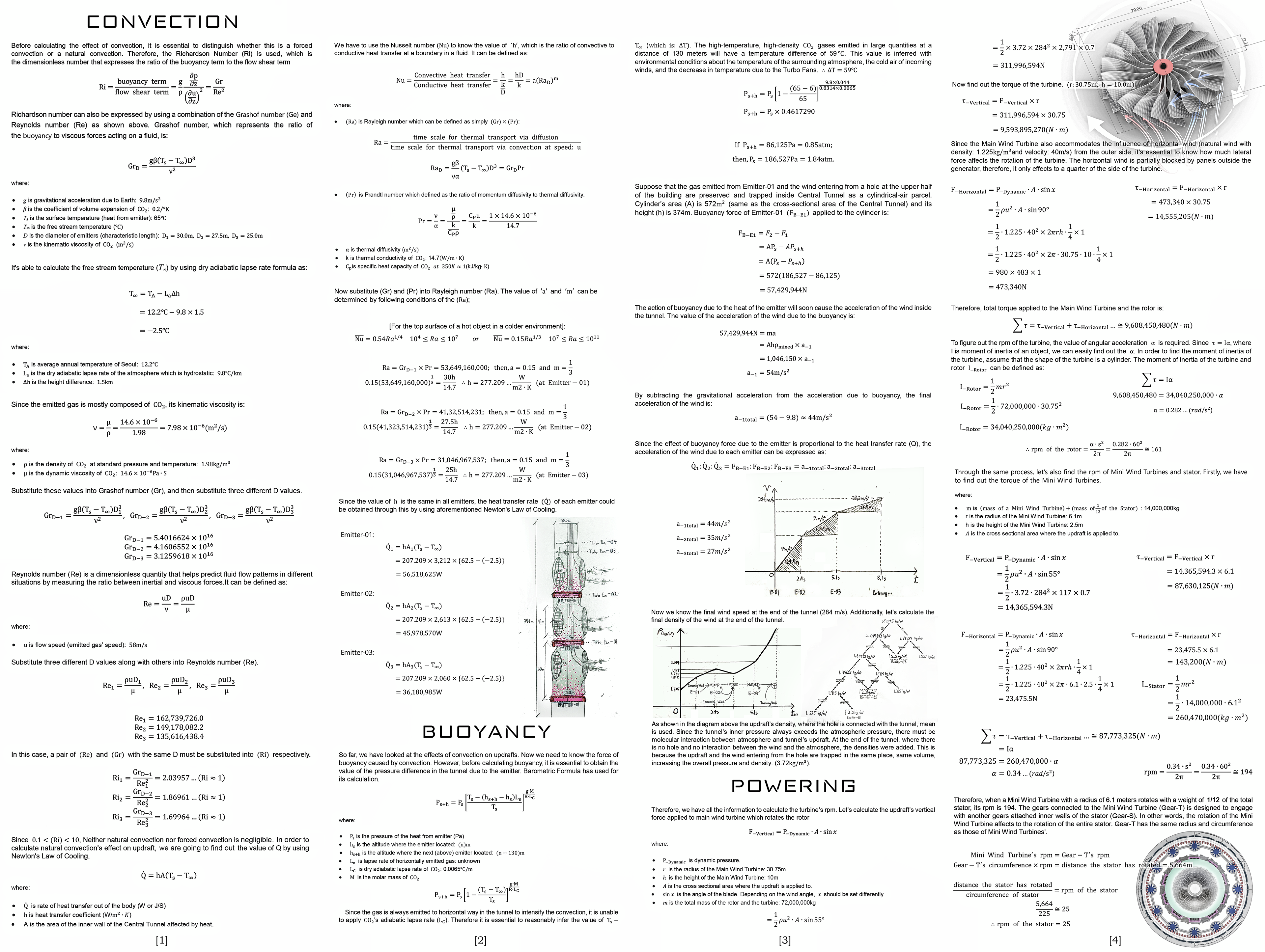
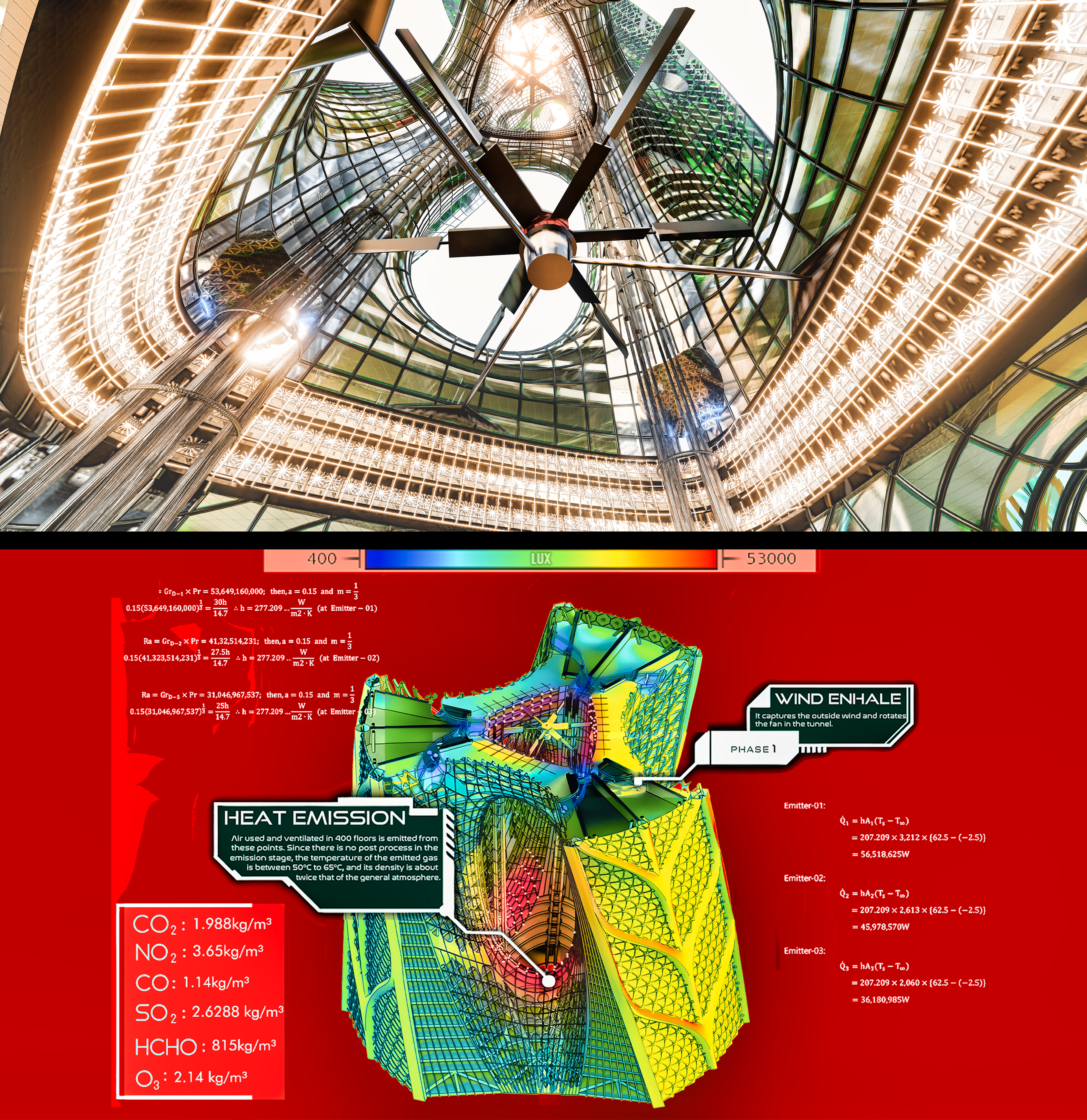
Another way to generate updrafts is to use convection. Air used and ventilated in 450 floors is emitted from the bottom of each hole in the Central Tunnel. Since there is no post process in the emission stage, the temperature of the emitted gas is between 50°C~65°C (or even higher) and its density is about twice that of the general atmosphere. (In addition, there are a total of three emitters inside the Central Tunnel, each called Emitter-01, Emitter-02, and Emitter-03 in the order of height placed)
Therefore, the density of the wind trapped in the tunnel increases significantly on average, and at the same time, convection occurs, causing an updraft. The increased density of the wind increases the kinetic energy of the wind and has a greater influence on power generation.
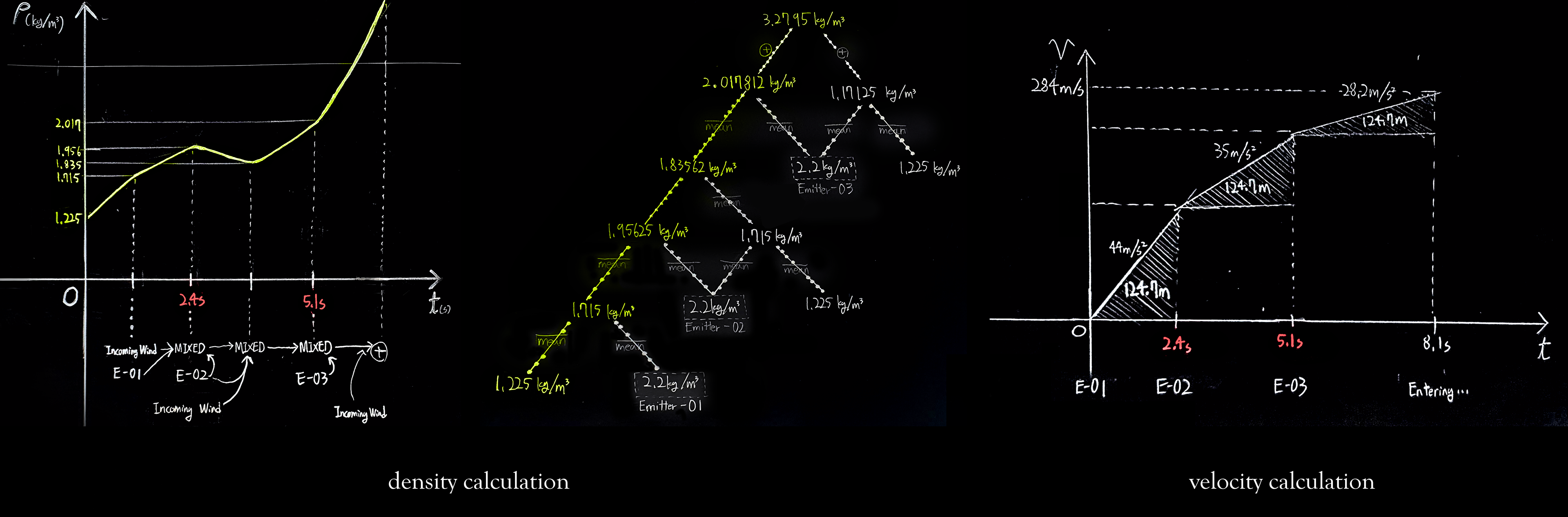
Since the temperature and density suddenly increased in certain parts of the Central Tunnel, there will also be a difference in pressure inside the tunnel. The pressure difference means buoyancy, and in addition to convection, buoyancy force will maximize the synergistic effect. From the calculation, the pressure difference in the tunnel between Emitter-01 and right below part of the Emitter-02 is about 100,000 Pa (which is about 1 atm), and the wind acceleration due to buoyancy is 44 m/s² at this point.
Along with convection and buoyancy, the Turbo Fan (244 rpm) will maximize the wind's rising power, and this updraft finally heads to the Mini Wind Tunnel and Main Wind Tunnel at the bottom of the generator.
EMITTERS (Outdoor Unit Layer)
All gases used inside in the building are emitted through the outdoor unit layers (Emitters) inside the Central Tunnel. Emitted gases will increase pressure and density in certain parts of the Central Tunnel and will maximize convection and buoyancy.
The render on the left shows the Emitter-01, where has the heat transfer rate of 56,518,625W.
The drawing on the right shows the entire structure of the Central Tunnel. Three emitters, four Turbo Fans and barriers are represented.
DETAILS
Compare the three graphs and focus the colored parts of each graph. In Velocity calculation, the area of a triangle (the distance traveled by the wind) is 124.7m, which is the distance from the top surface of the emitter below to the bottom surface of the emitter above. In density calculation, focus on the middle graph's colored part, which represents the change in density according to the height of the updraft. This change is affected by the heat of each emitted gas and the surrounding atmosphere (Check the sketch of Central Tunnel above or third board for better understanding). In additian, the number 1.225 kg/m³ is the density of the atmosphere, which indicates the initial entering wind through the holes at upper half. Therefore, by using the data (colored) in the middle graph, we can draw another graph which shows the density change over time (left graph). The graph shows that the density of the updraft at the end of the tunnel is 3.3kg/m³. For more details, check out the third board (the full calculation).
Phase 3: POWERING
The updraft generated in the Central Tunnel is directed to the generator. Before entering the generator, the wind is divided into two types of tunnels. The wind released from [Main Wind Tunnels] rotates a massive 72,000-ton Main Turbine, which is connected to the Rotor. The wind released from [Mini Wind Tunnel] rotates 12 small Mini Turbines which are connected to the Stator. Since all of the Mini-Turbine's blades are opposite of the Main Turbine’s, the Stator and Rotor rotate in opposite directions (by using its unique gear structures) unlike general powering method that rotates only the rotor. Calculation suggests in an ordinary day, the Rotor has 161rpm and Stator has 25rpm.
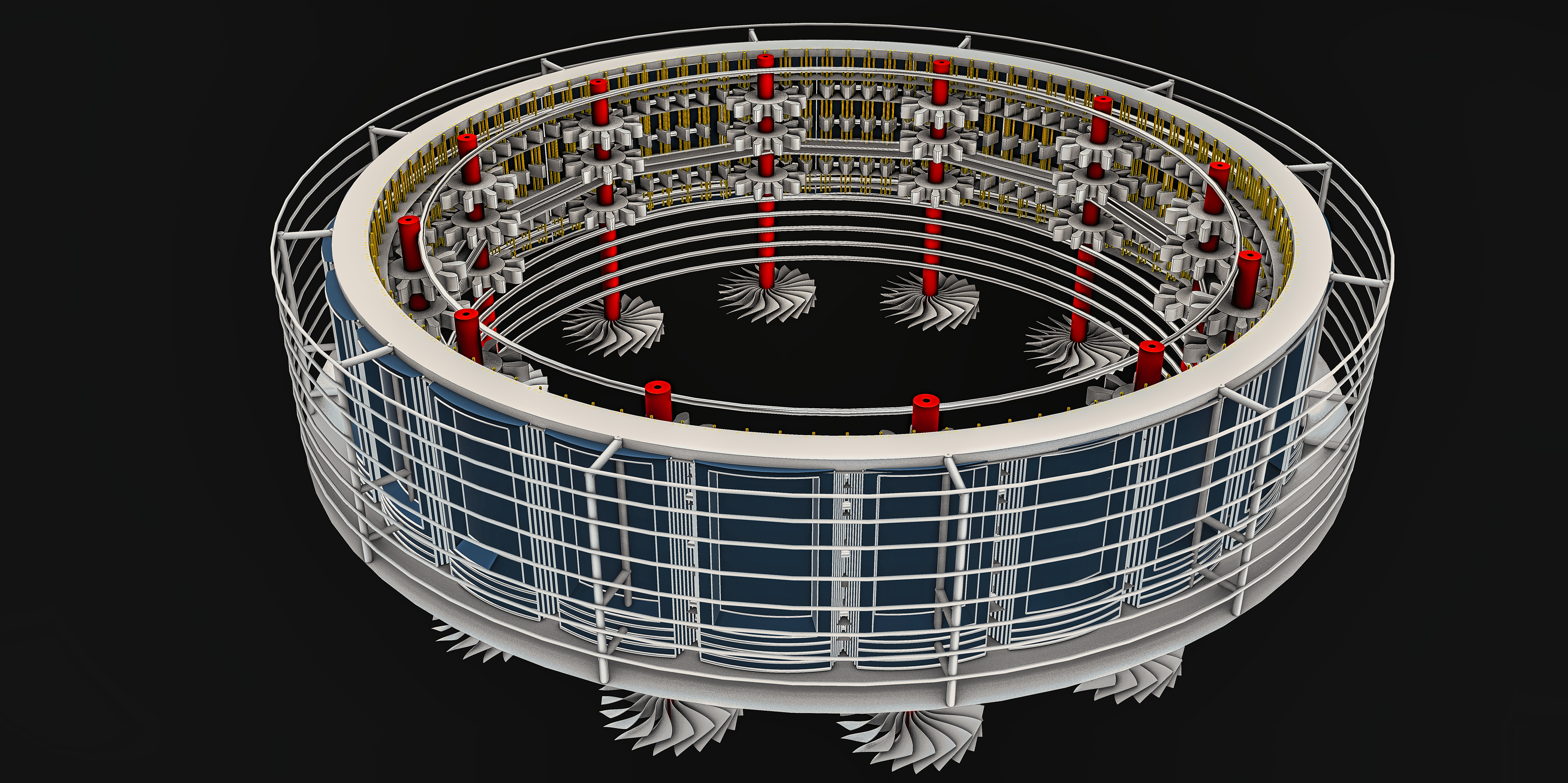
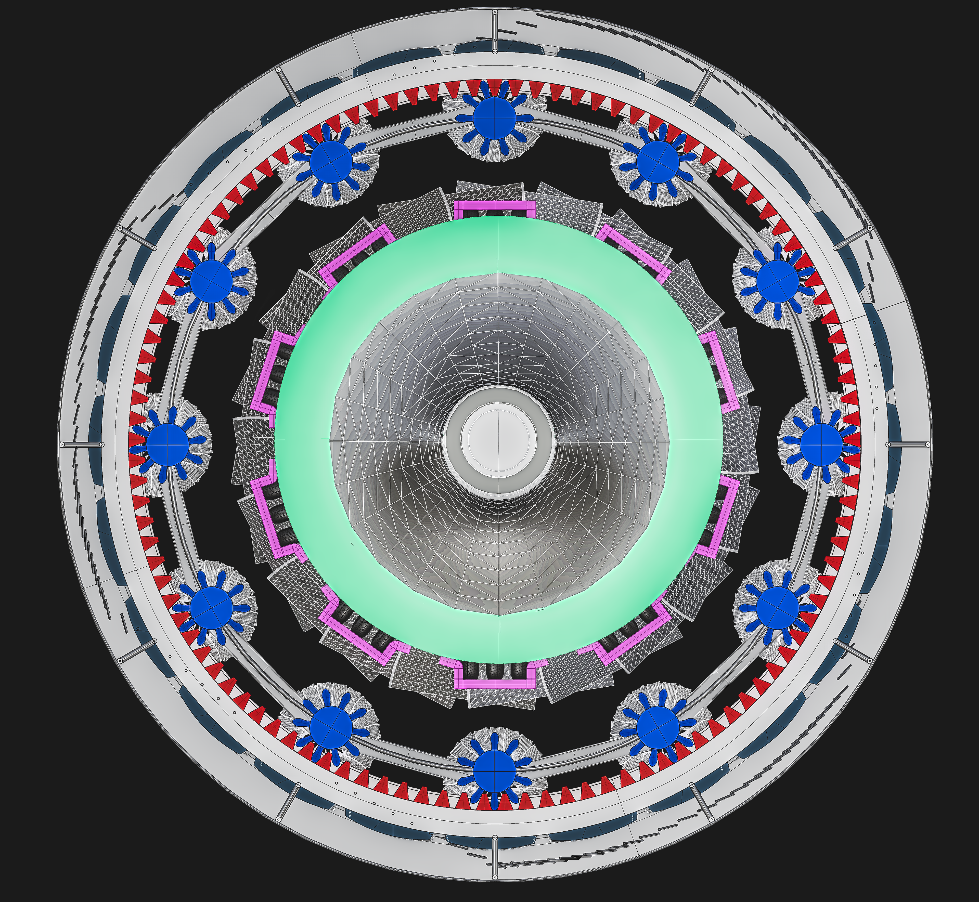
Isolated Stator
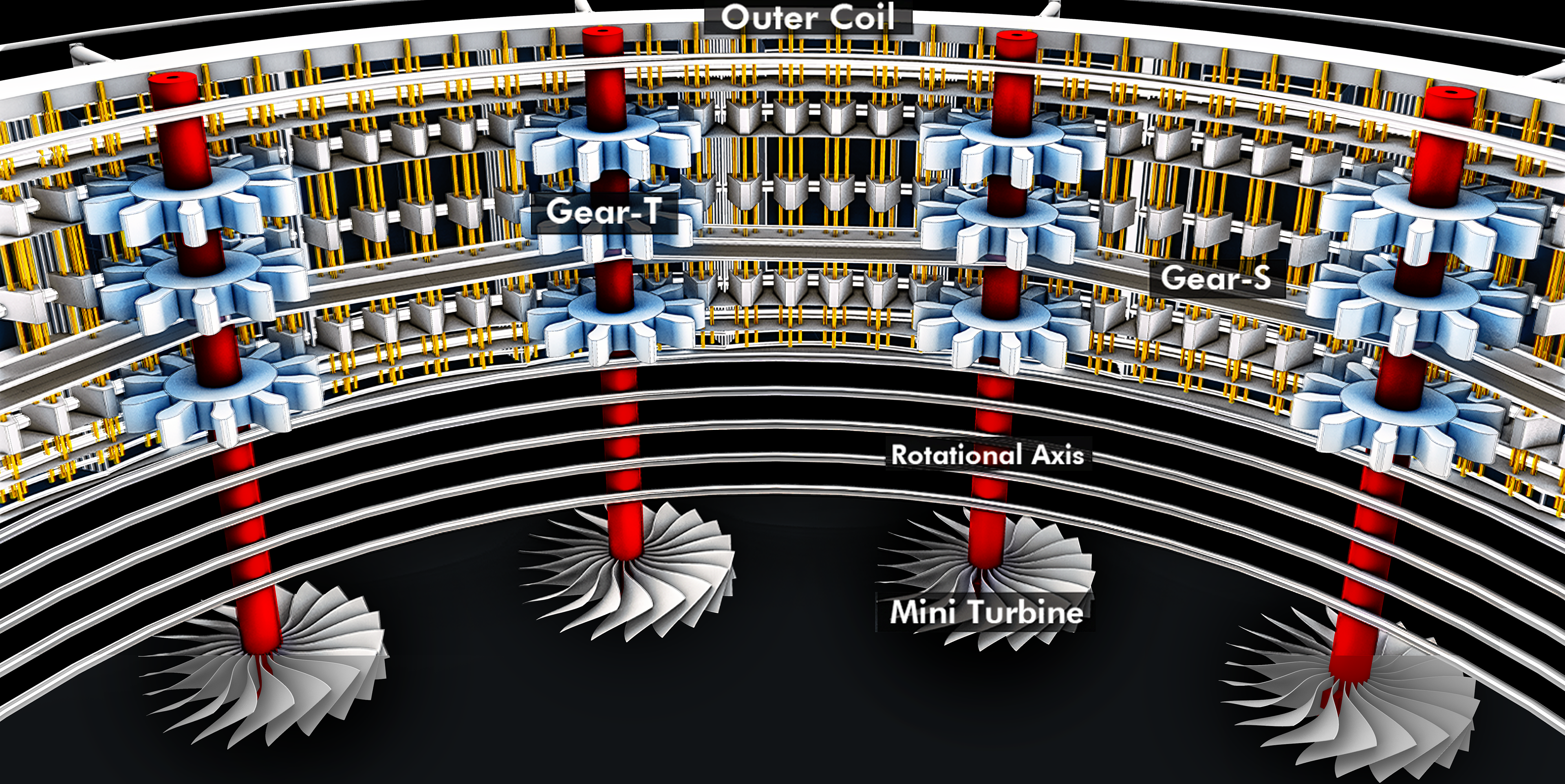
GEARS
The diagram shows the structure of the gears that cause the rotation of the Stator. Gear-T, which is connected to the rotational axis (red columns), exactly follows the rotation of the Mini Wind Turbine below. Due to the rotation of the Gear-T, Gear-S, which attached along the inner surface of the Stator, starts to rotate.
Assume that all Gear-T are pushing Gear-S with same force (with same rotation per minute of 194). The rpm value of the Stator can be obtained by comparing the circumference of the inner surface of the stator with the circumference of the Gear-T. Calculation suggests in an ordinary day, the Stator has 25rpm.
Comparing one turbine of Three Gorges Dam with a performance of 700 MW, Ascending Dragon's generator will provide much greater power (if the wind blows at a constant speed).

HYPOTHESIS
As shown in phases 1 and 2 above, the air entering the Central Tunnel of the building will become a radical updraft by convection and fans. At this time, if environmental conditions are satisfied, there is a possibility that a whirlwind will occur in the building.
Minor whirlwinds, such as dust devil, form when a pocket of hot air near the surface rises quickly through cooler air above it, forming an updraft. If conditions are just right, the updraft may begin to rotate. As the column of hot air stretched vertically, the spinning effect becomes further intensified and self-sustaining due to multiple factors (conservation of angular momentum or the secondary flow).
The Central Tunnel has sufficient conditions for the creation of whirlwinds. As Phase 2 suggests, not only is the temperature difference between the upper and lower portions of the tunnel severe, but there is also a difference in atmospheric pressure. As Phase 1 suggests, the four Turbo Fans inside the tunnel will maximize the air rise effect along with convection.
If a whirlwind occurs in the tunnel, it will have a profound effect on the rotation of the turbine just above of it. The rotation of the turbine is related to power generation of the generator, so the whirl in the tunnel must be considered as an important factor.
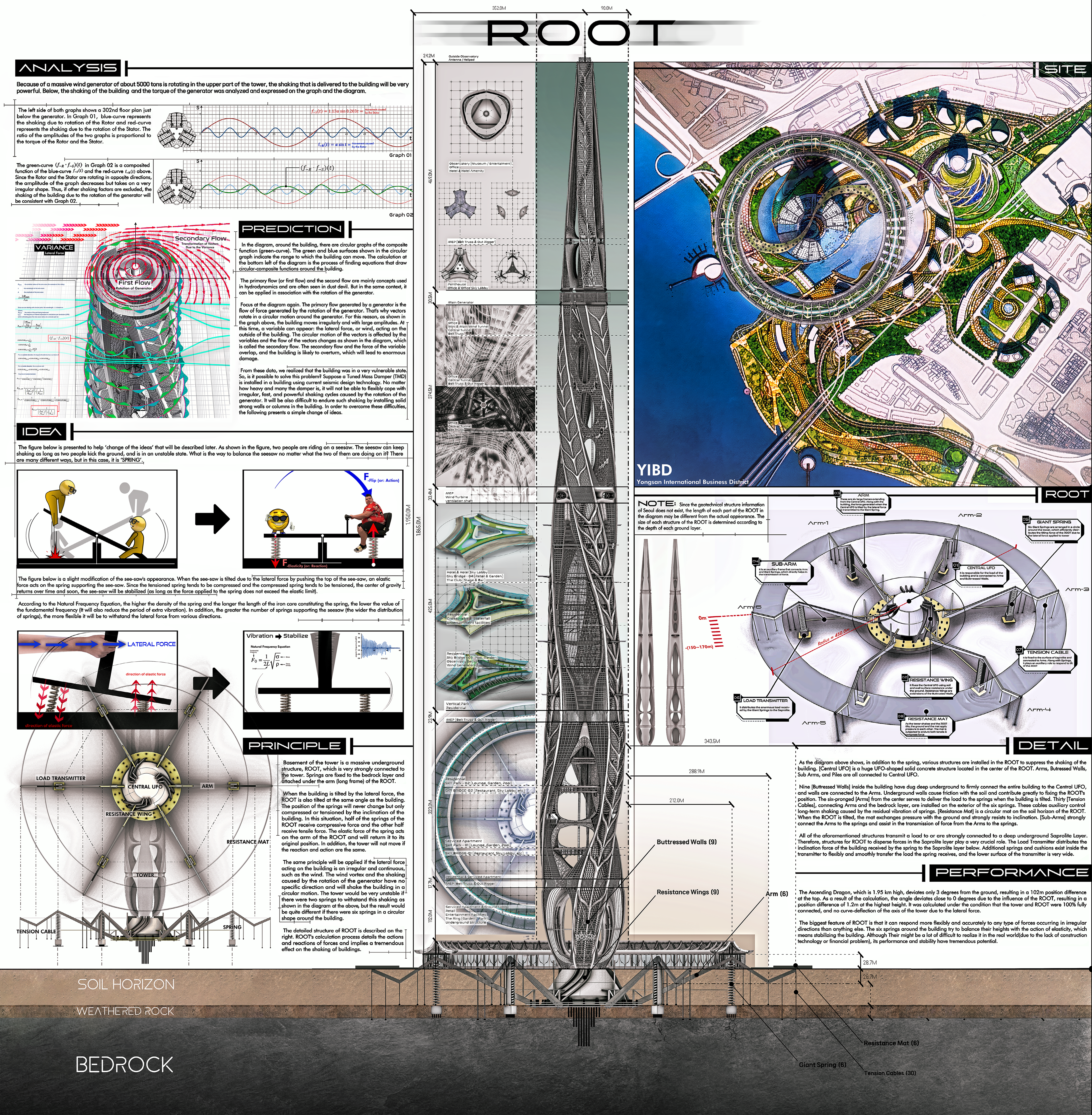
ANALYSIS
Because of a massive wind generator of about 170,000 tons is rotating in the upper part of the tower, the shaking that is delivered to the building must be very powerful. Below represents the shaking of the building and the torque of the generator was analyzed and expressed on the graph and the diagram.
(Some experts say that there may be no shaking of buildings caused by generators. But let me introduce my analysis anyways.)
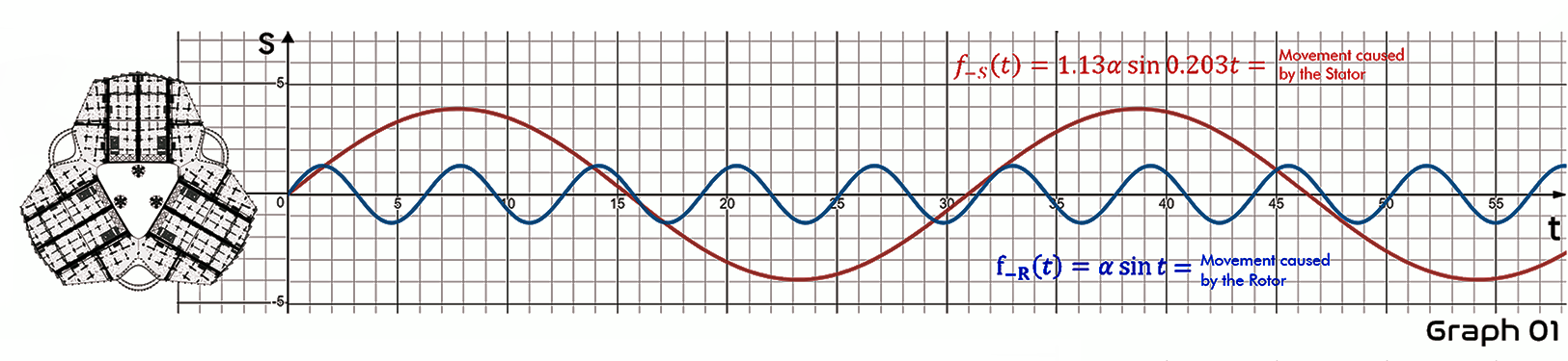
The left side of both graphs shows a 302nd floor plan just below the generator. In Graph 01, blue-curve represents the shaking due to rotation of the Rotor and red-curve represents the shaking due to the rotation of the Stator. The ratio of the amplitudes of the two graphs is proportional to the torque of the Rotor and the Stator.
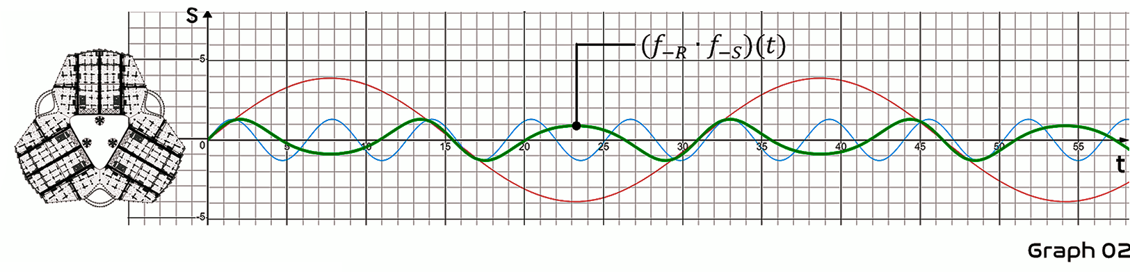
The green-curve (f-r'f-s)(t) in Graph 02 is a composited function of the blue-curve f-s(t) and the red-curve f_R(t) above. Since the Rotor and the Stator are rotating in opposite directions, the amplitude of the graph decreases but takes on a very irregular shape. Thus, if other shaking factors are excluded, the shaking of the building due to the rotation of the generator will be consistent with Graph 02.
PREDICTION
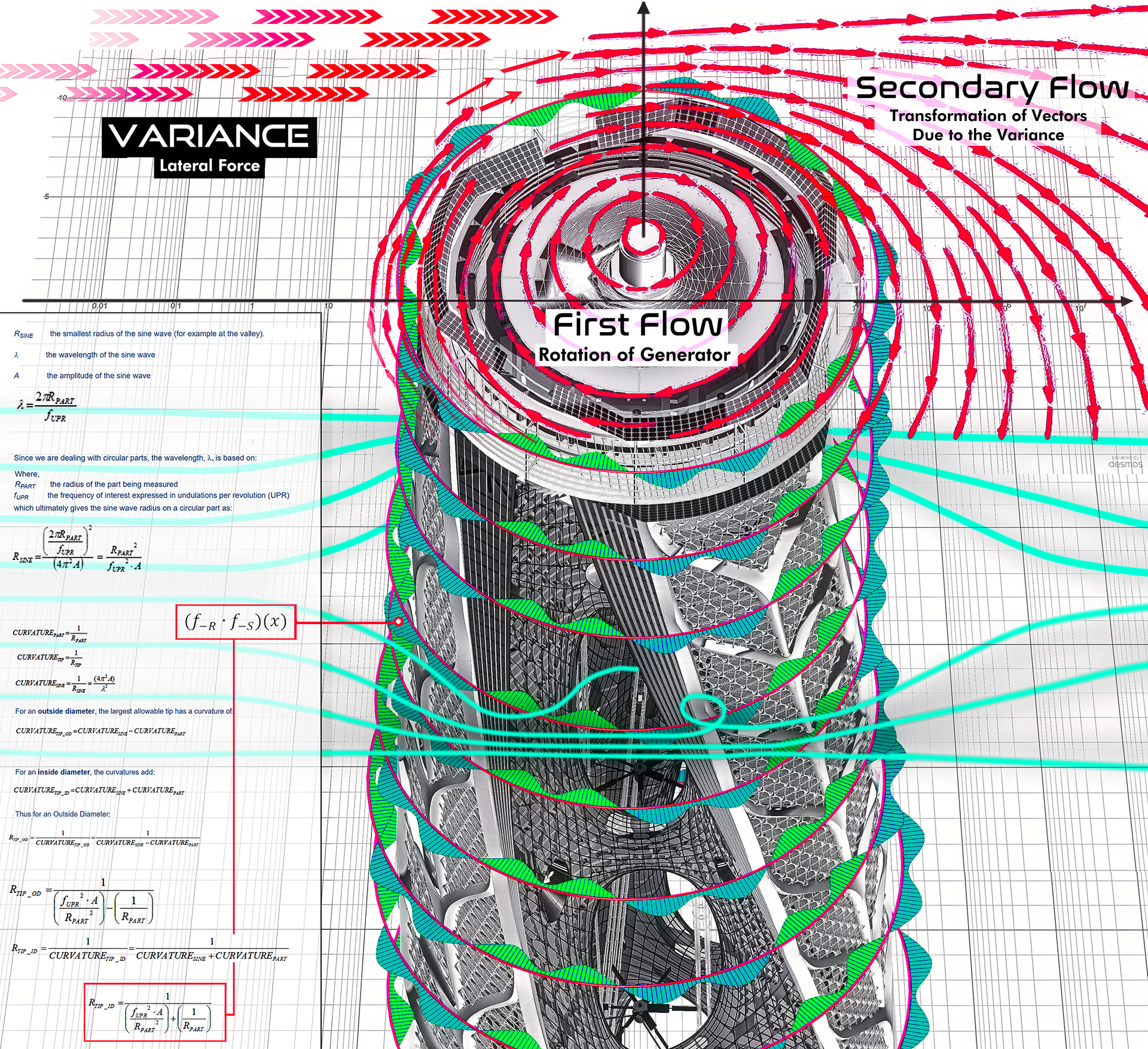
In the diagram, around the building, there are circular graphs of the composite function (green-curve). The green and blue surfaces shown in the circular graph indicate the range to which the building can move. The calculation at the bottom left of the diagram is the process of finding equations that draw circular-composite functions around the building.
The primary flow (or first flow) and the second flow are mainly concepts used in hydrodynamics and are often seen in dust devil. But in the same context, it can be applied in association with the rotation of the generator.
Focus at the diagram again. The primary flow generated by a generator is the flow of force generated by the rotation of the generator. That's why vectors rotate in a circular motion around the generator. For this reason, as shown in the graph above, the building moves irregularly and with large amplitudes. At this time, a variable can appear: the lateral force, or wind, acting on the outside of the building. The circular motion of the vectors is affected by the variables and the flow of the vectors changes as shown in the diagram, which is called the secondary flow. The secondary flow and the force of the variable overlap, and the building is likely to overturn, which will lead to enormous damage.
Focus at the diagram again. The primary flow generated by a generator is the flow of force generated by the rotation of the generator. That's why vectors rotate in a circular motion around the generator. For this reason, as shown in the graph above, the building moves irregularly and with large amplitudes. At this time, a variable can appear: the lateral force, or wind, acting on the outside of the building. The circular motion of the vectors is affected by the variables and the flow of the vectors changes as shown in the diagram, which is called the secondary flow. The secondary flow and the force of the variable overlap, and the building is likely to overturn, which will lead to enormous damage.
From these data, we realized that the building was in a very vulnerable state. So, is it possible to solve this problem? Suppose a Tuned Mass Damper (TMD) is installed in a building using current seismic design technology. No matter how heavy and many the damper is, it will not be able to flexibly cope with irregular, fast, and powerful shaking cycles caused by the rotation of the generator. It will be also difficult to endure such shaking by installing solid strong walls or columns in the building. In order to overcome these difficulties, the following presents a simple change of ideas.
IDEA
The figure on the right is presented to help 'change of the ideas' that will be described later. As shown in the figure, two nerds are riding on a seesaw. The seesaw can keep shaking as long as two nerds kick the ground, and is in an unstable state. What is the way to balance the seesaw no matter what the two of them are doing on it? There are many different ways, but in this case, it is 'SPRING'.
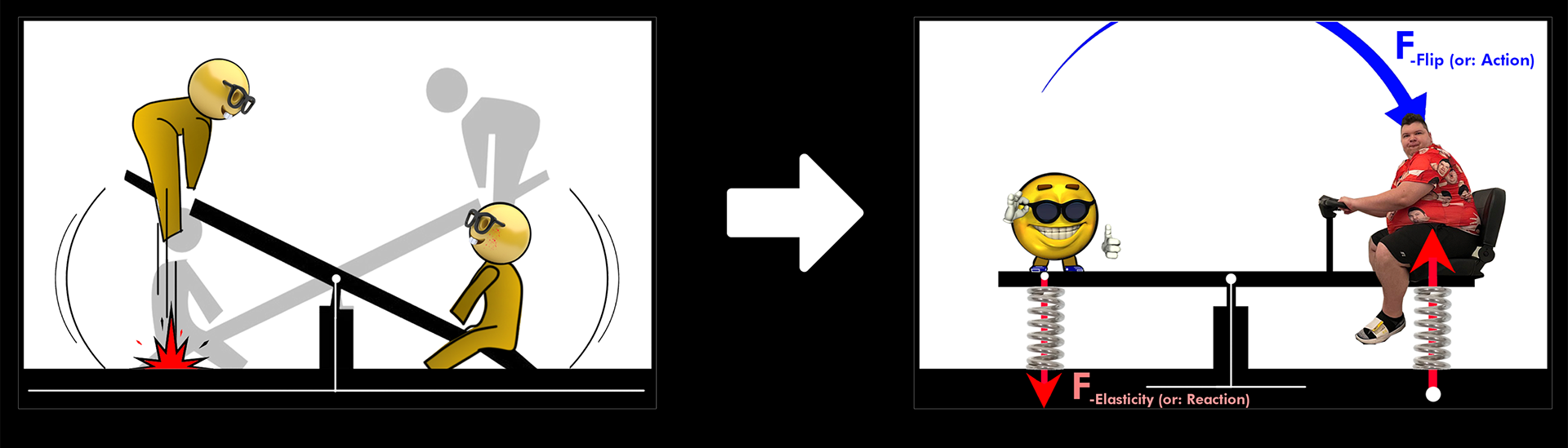
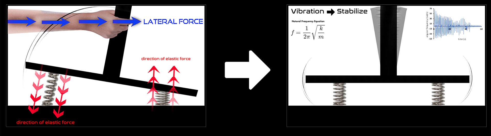
The figure on the right is a slight modification of the see-saw's appearance. When the see-saw is tilted due to the lateral force by pushing the top of the see-saw, an elastic force acts on the spring supporting the see-saw. Since the tensioned spring tends to be compressed and the compressed spring tends to be tensioned, the center of gravity returns over time and soon, the see-saw will be stabilized (as long as the force applied to the spring does not exceed the elastic limit).
PRINCIPLE
Basement of the tower is a massive underground structure, ROOT, which is very strongly connected to the tower. Springs are fixed to the bedrock layer and attached under the arm (long frame) of the ROOT.
When the building is tilted by the lateral force, the ROOT is also tilted at the same angle as the building. The position of the springs will never change but only compressed or tensioned by the inclination of the building. In this situation, half of the springs of the ROOT receive compressive force and the other half receive tensile force. The elastic force of the spring acts on the arm of the ROOT and will return it to its original position. In addition, the tower will not move if the reaction and action are the same.
The same principle will be applied if the lateral force acting on the building is an irregular and continuous, such as the wind. The wind vortex and the shaking caused by the rotation of the generator have no specific direction and will shake the building in a circular motion. The tower would be very unstable if there were two springs to withstand this shaking as shown in the diagram at the above, but the result would be quite different if there were six springs in a circular shape around the building.
The detailed structure of ROOT is described on the right. ROOT's calculation process details the actions and reactions of forces and implies a tremendous effect on the shaking of buildings.
DETAILS
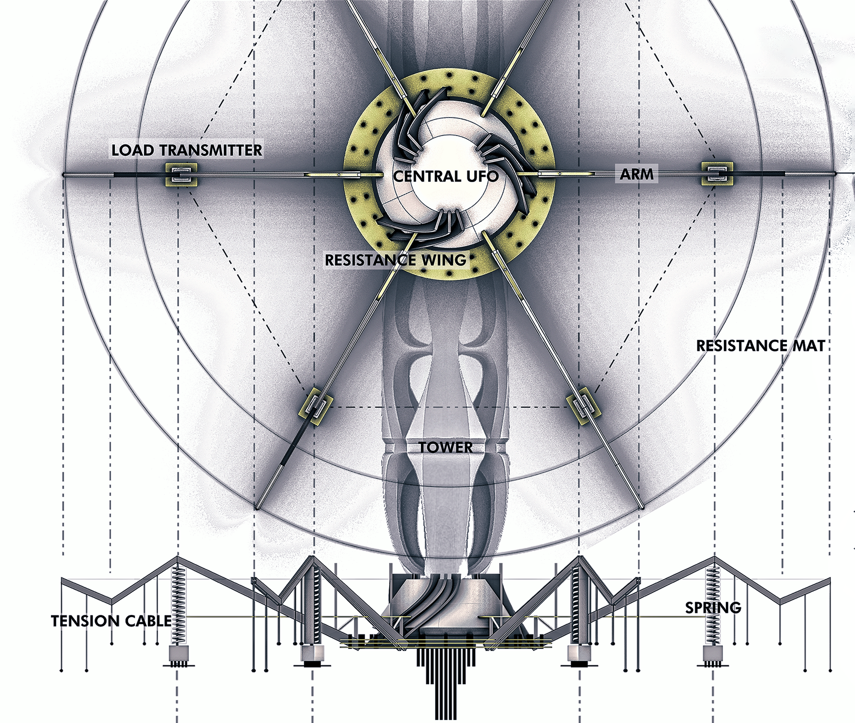
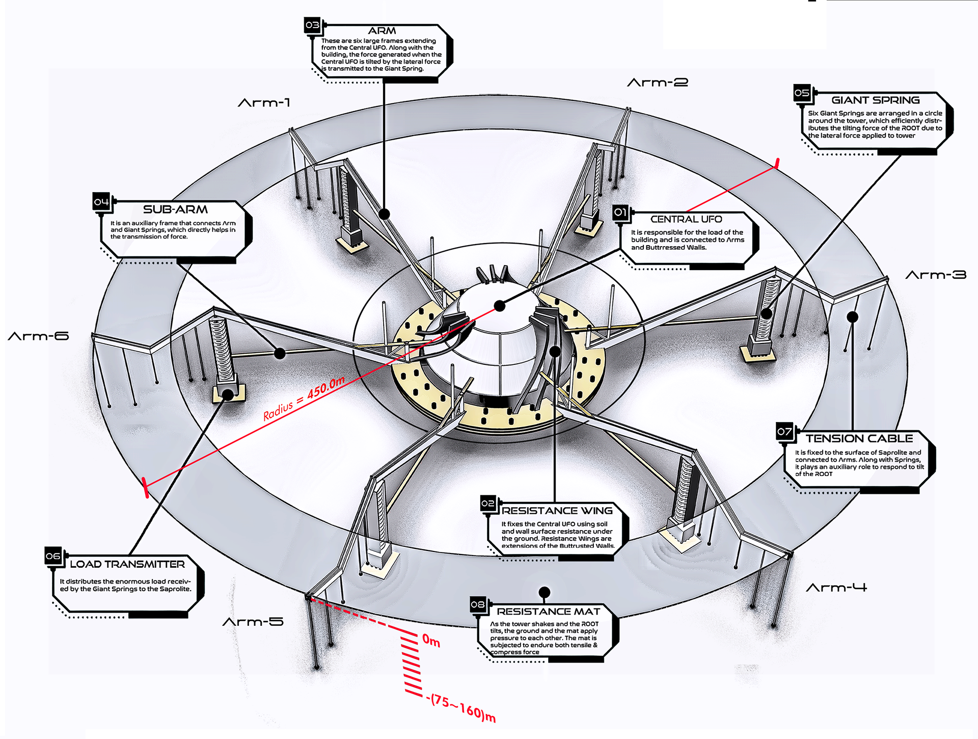
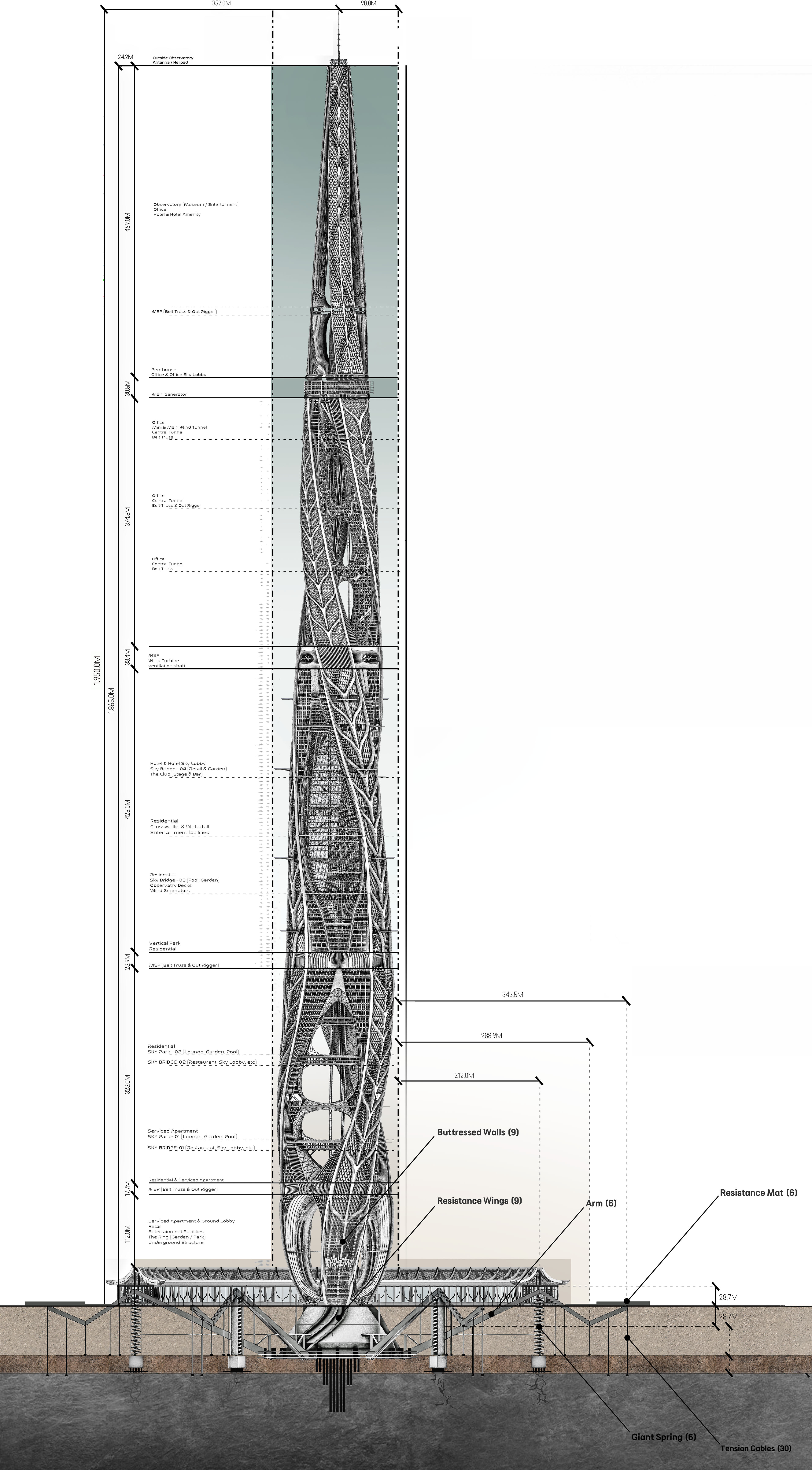
As the diagram above shows, in addition to the spring, various structures are installed in the ROOT to suppress the shaking of the building. [Central UFO] is a huge UFO-shaped solid concrete structure located in the center of the ROOT. Arms, Butressed Walls, Sub Arms, and Piles are all connected to Central UFO.
Nine [Buttressed Walls] inside the building have dug deep underground to firmly connect the entire building to the Central UFO, and walls are connected to the Arms. Underground walls cause friction with the soil and contribute greatly to fixing the ROOT's position. The six-pronged [Arms] from the center serves to deliver the load to the springs when the building is tilted. Thirty [Tension Cables], connecting Arms and the bedrock layer, are installed on the exterior of the six springs. These cables auxiliary control long-term shaking caused by the residual vibration of springs. [Resistance Mat] is a circular mat on the soil horizon of the ROOT. When the ROOT is tilted, the mat exchanges pressure with the ground and strongly resists to inclination. [Sub-Arms] strongly connect the Arms to the springs and assist in the transmission of force from the Arms to the springs.
All of the aforementioned structures transmit a load to or are strongly connected to a deep underground Saprolite Layer. Therefore, structures for ROOT to disperse forces in the Saprolite layer play a very crucial role. The Load Transmitter distributes the inclination force of the building received by the spring to the Saprolite layer below. Additional springs and cushions exist inside the transmitter to flexibly and smoothly transfer the load the spring receives, and the lower surface of the transmitter is very wide.
PERFORMANCE
The Ascending Dragon, which is 1.95 km high, deviates only 3 degrees from the ground, resulting in a 102m position difference at the top. As a result of the calculation, the angle deviates close to 0 degrees due to the influence of the ROOT, resulting in a position difference of 1.2m at the highest height. It was calculated under the condition that the tower and ROOT were 100% fully connected, and no curve-deflection of the axis of the tower due to the lateral force.
The Ascending Dragon, which is 1.95 km high, deviates only 3 degrees from the ground, resulting in a 102m position difference at the top. As a result of the calculation, the angle deviates close to 0 degrees due to the influence of the ROOT, resulting in a position difference of 1.2m at the highest height. It was calculated under the condition that the tower and ROOT were 100% fully connected, and no curve-deflection of the axis of the tower due to the lateral force.
The biggest feature of ROOT is that it can respond more flexibly and accurately to any type of forces occurring in irregular directions than anything else. The six springs around the building try to balance their heights with the action of elasticity, which means stabilizing the building. Although Their might be a lot of difficult to realize it in the real world(due to the lack of construction technology or financial problem), its performance and stability have tremendous potential.
LOOP (YIBD)
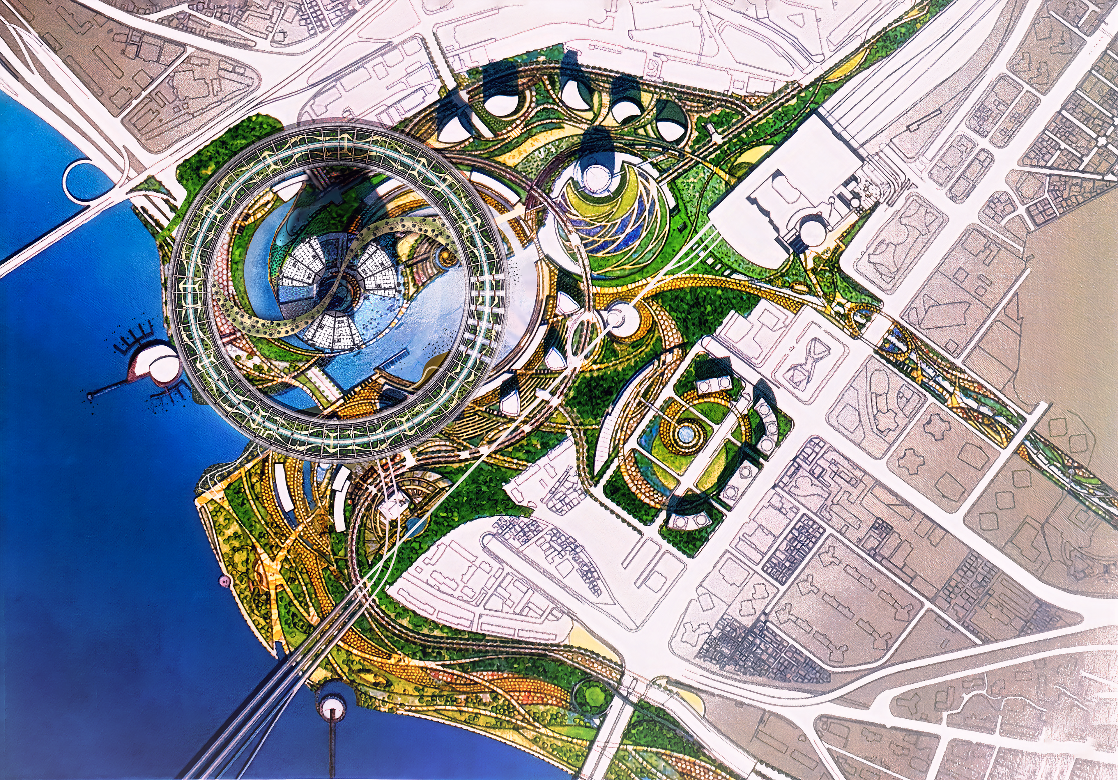
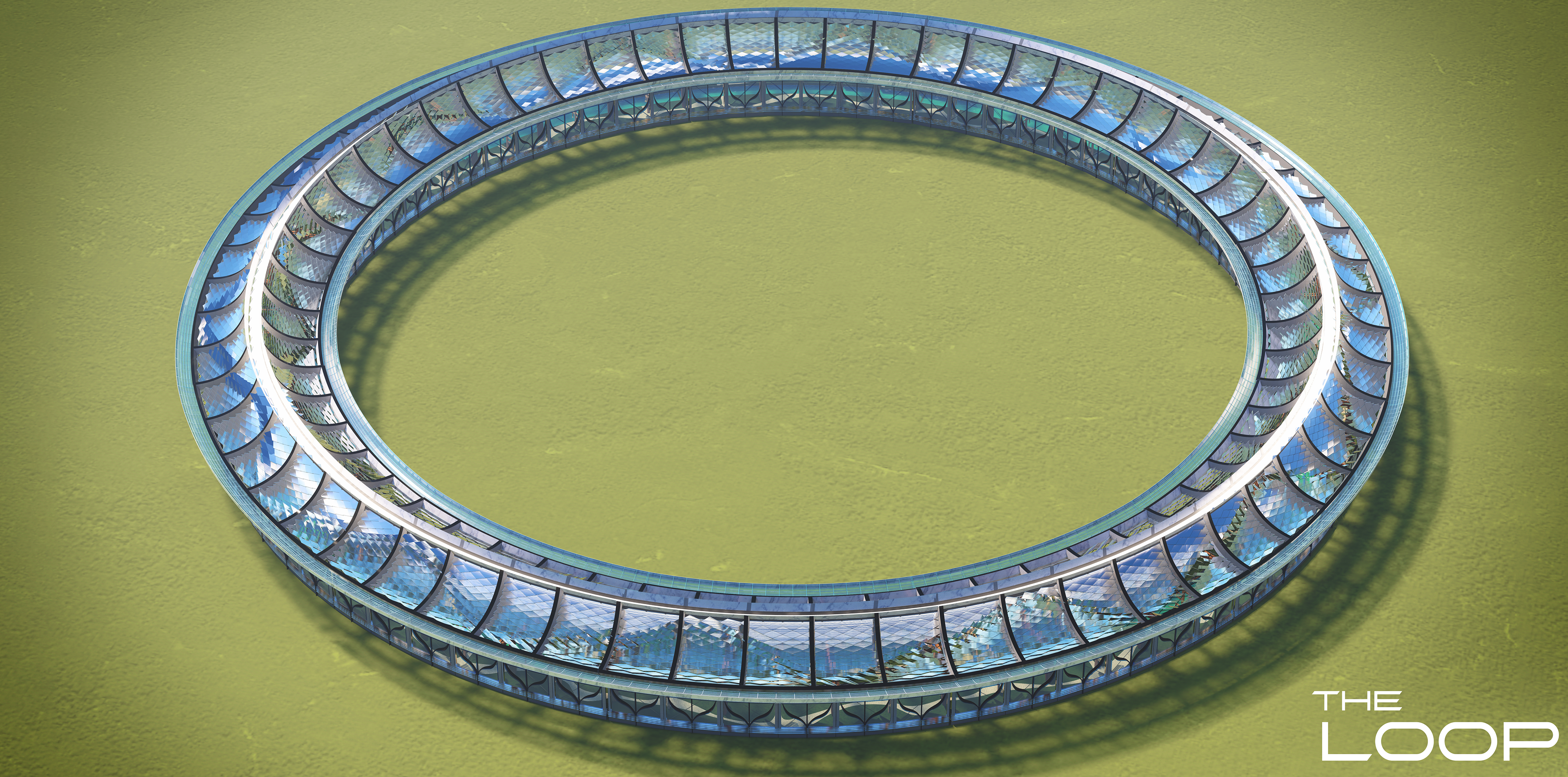
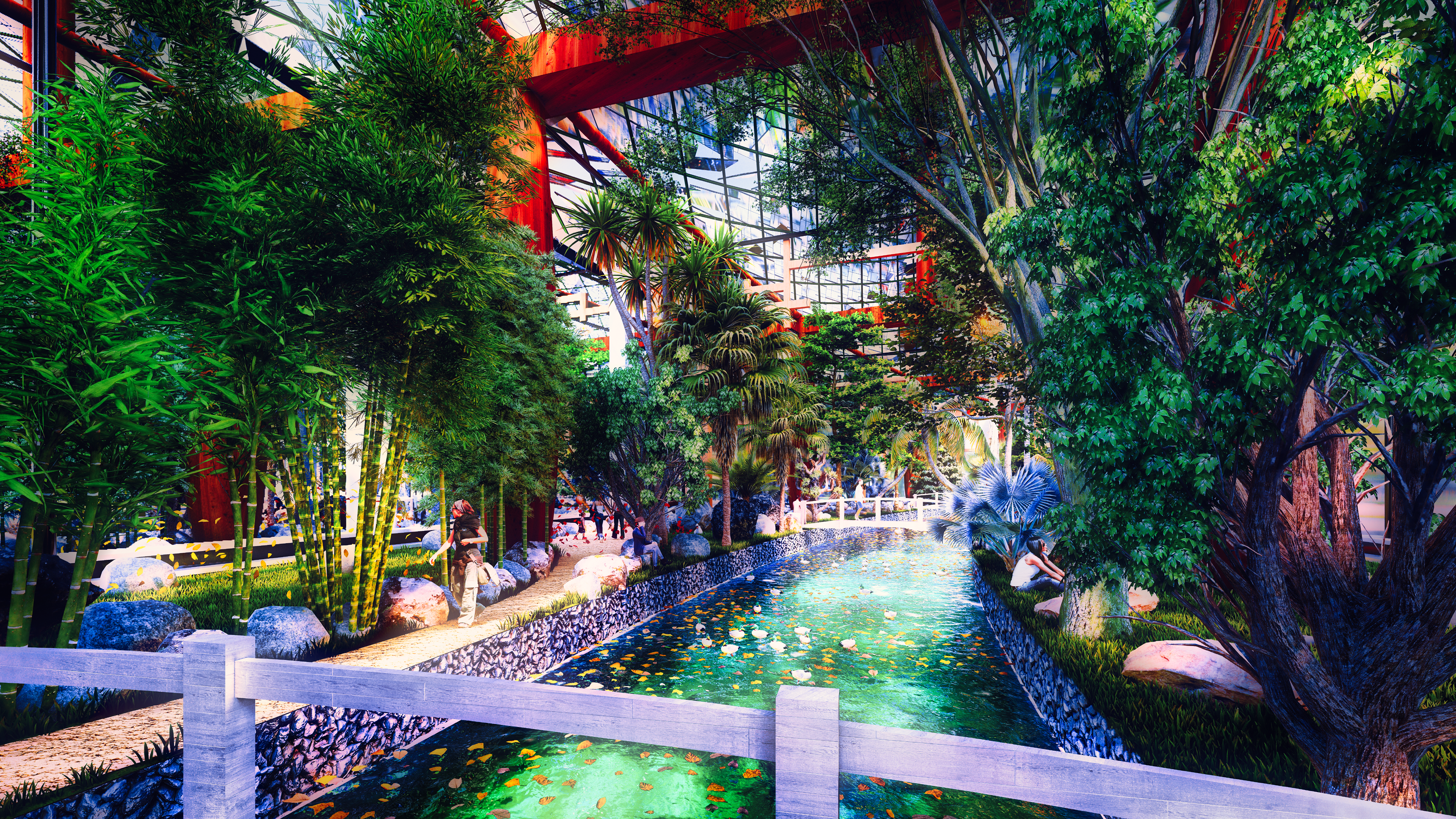
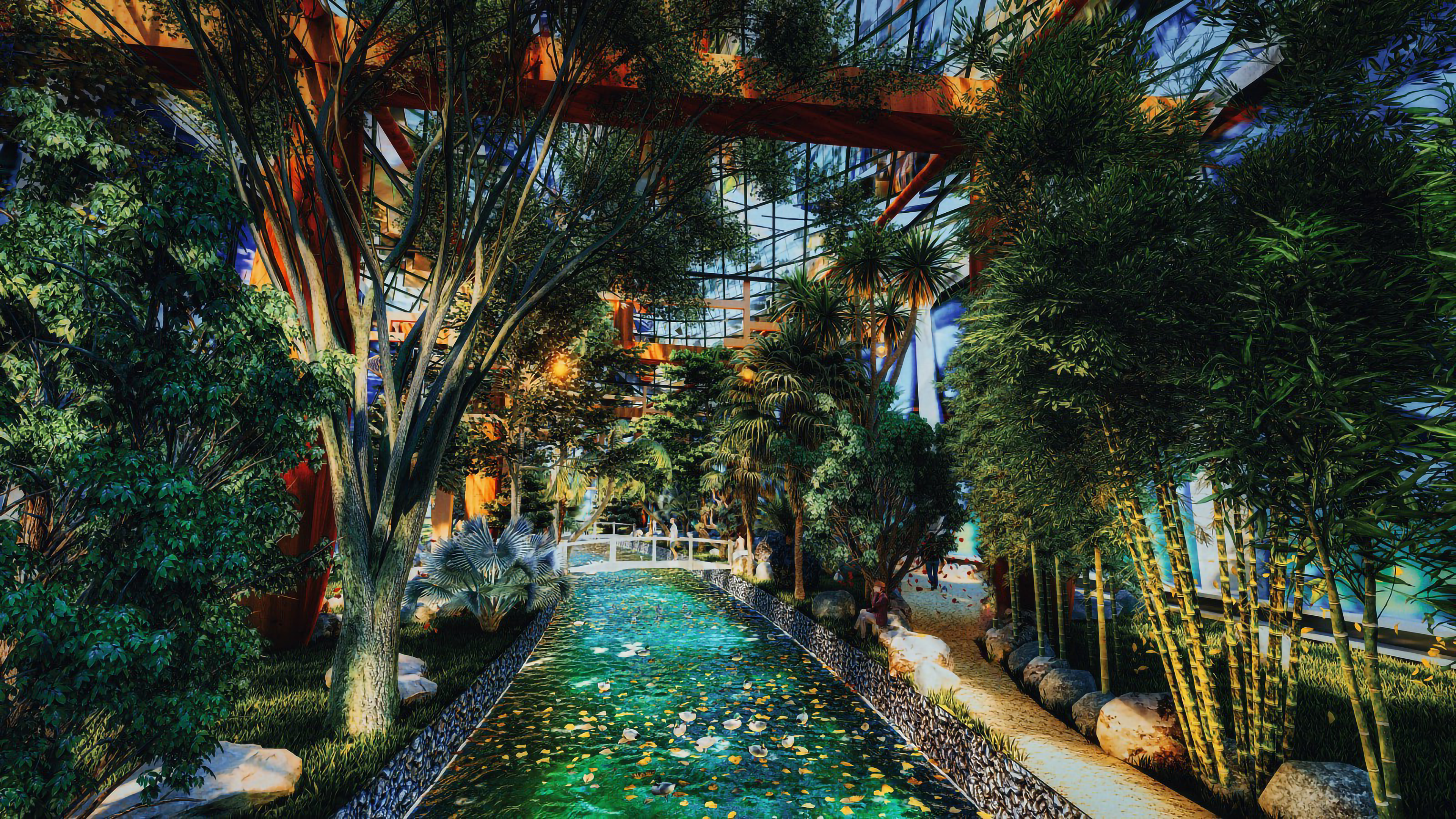
As can be seen in the diagram above, the part where the ROOT protrudes out of the ground is covered by an annular architecture: The Loop, which is a huge garden, 704 meters in diameter and 35 meters in height, and its structure resembles traditional Korean architecture. The upper part of the Loop has a roof similar to the dragon's scales (same as the curtain wf the main tower), and the inner column consists of a wooden entasis.
THE LOOP
THE LOOP
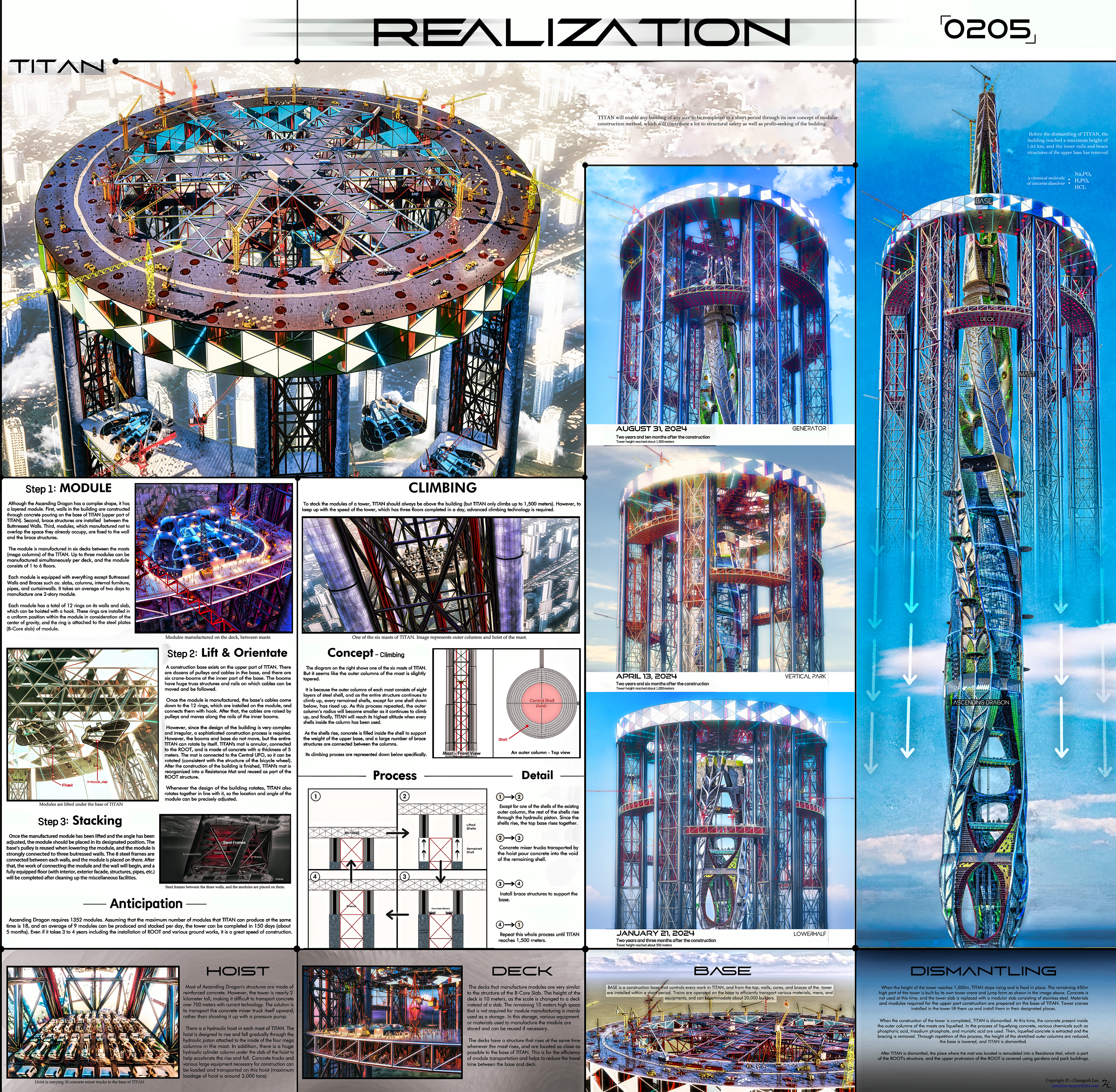
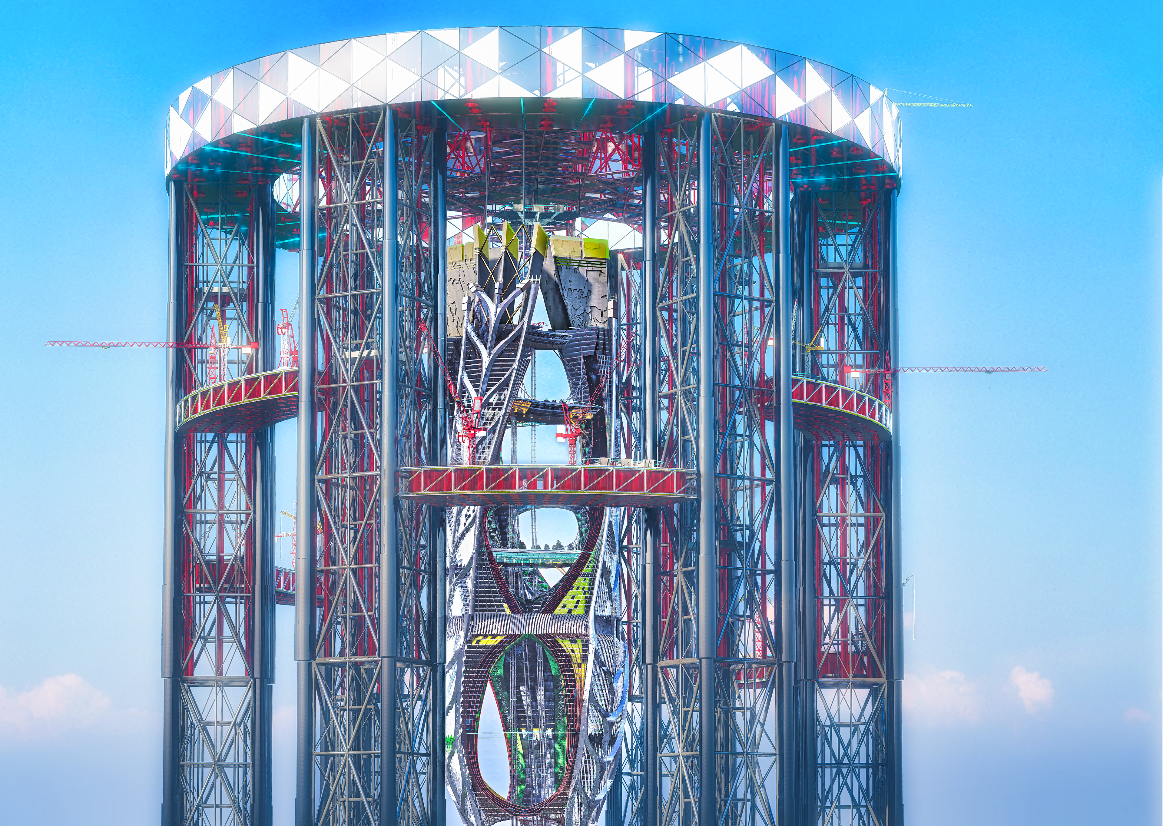
TITAN is the construction stronghold that facilitates efficient tower construction.
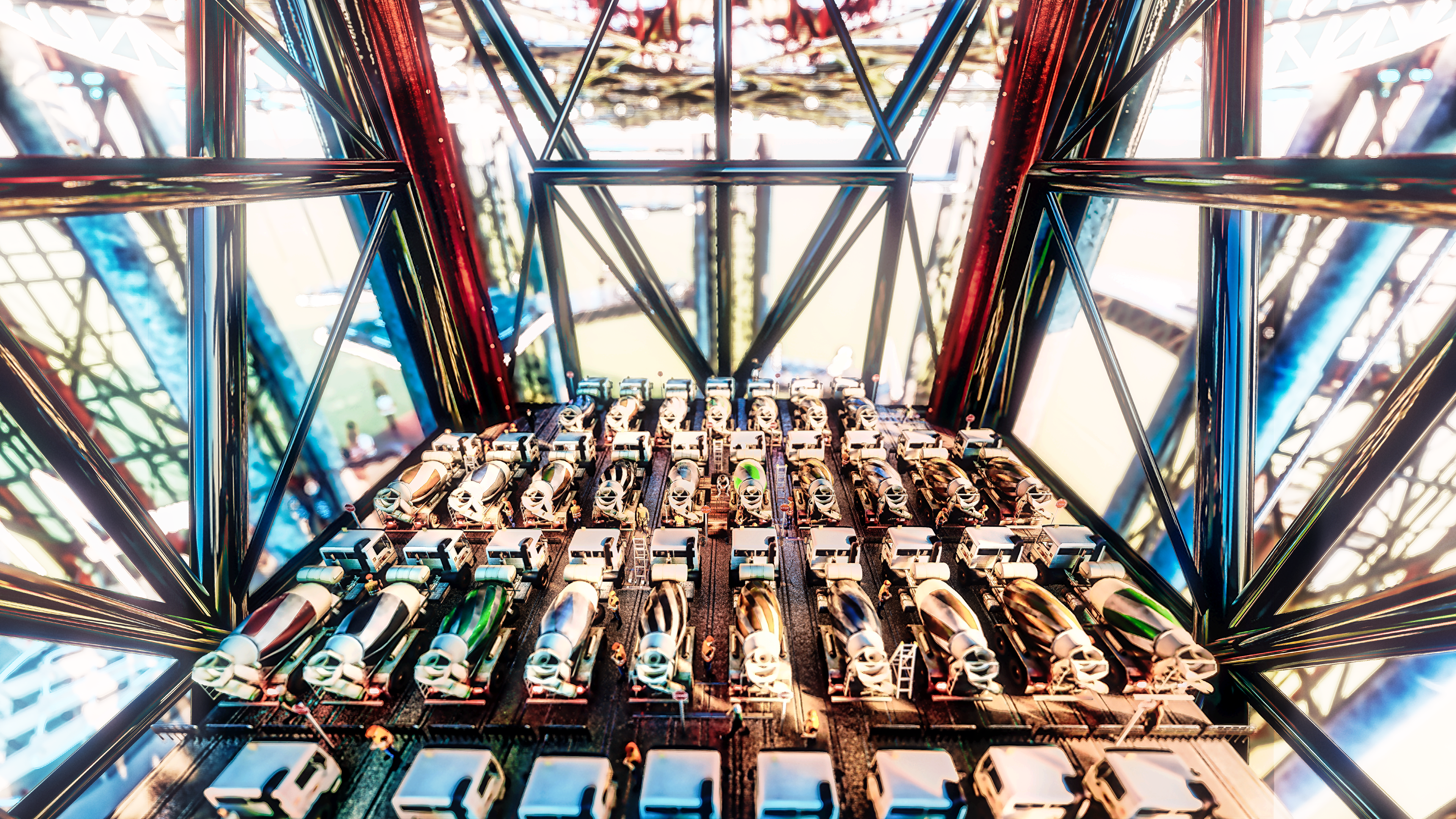
HOIST
Most of Ascending Dragon's structures are made of reinforced concrete. However, the tower is nearly 2 km tall, making it difficult to transport concrete over 700 meters with current technology. The solution is to transport the concrete mixer truck itself upward, rather than shooting it up with a pressure pump.
There is a hydraulic hoist in each mast of TITAN. The hoist is designed to rise and fall gradually through the hydraulic piston attached to the inside the four mega columns in the mast. In addition, there is a massive hydraulic cylinder under the slab of the hoist to help accelerate the rise and fall. Concrete trucks and various large equipment necessary for construction can be loaded and transported on this hoist (maximum loadage of hoist is around 3,000 tons).
DECK
The decks that manufacture modules are very similar to the structure of the B-Core Slab. The height of the deck is 10 meters, as the scale is changed to a deck instead of a slab. The remaining 10 meters high space that is not required for module manufacturing is mainly used as a storage. In this storage, various equipment or materials used to manufacture the module are stored and can be reused if necessary.
The decks have a structure that rises at the same time whenever the mast rises, and are located as close as possible to the base of TITAN. This is for the efficiency of module transportation and helps to reduce the travel time between the base and deck.
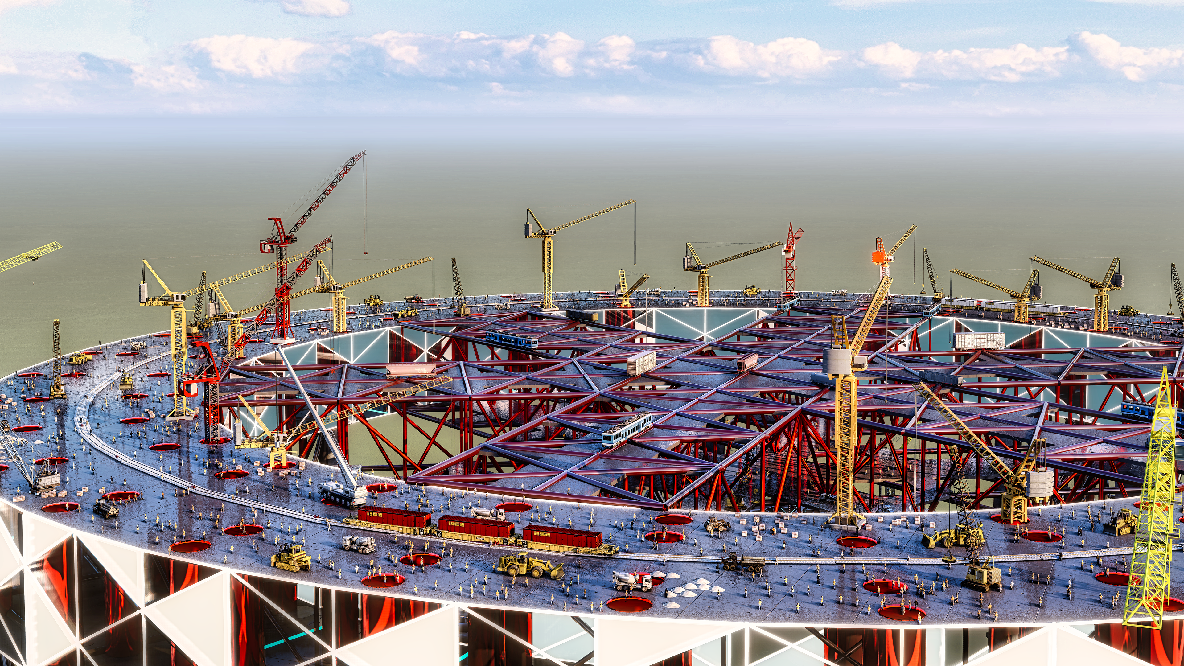
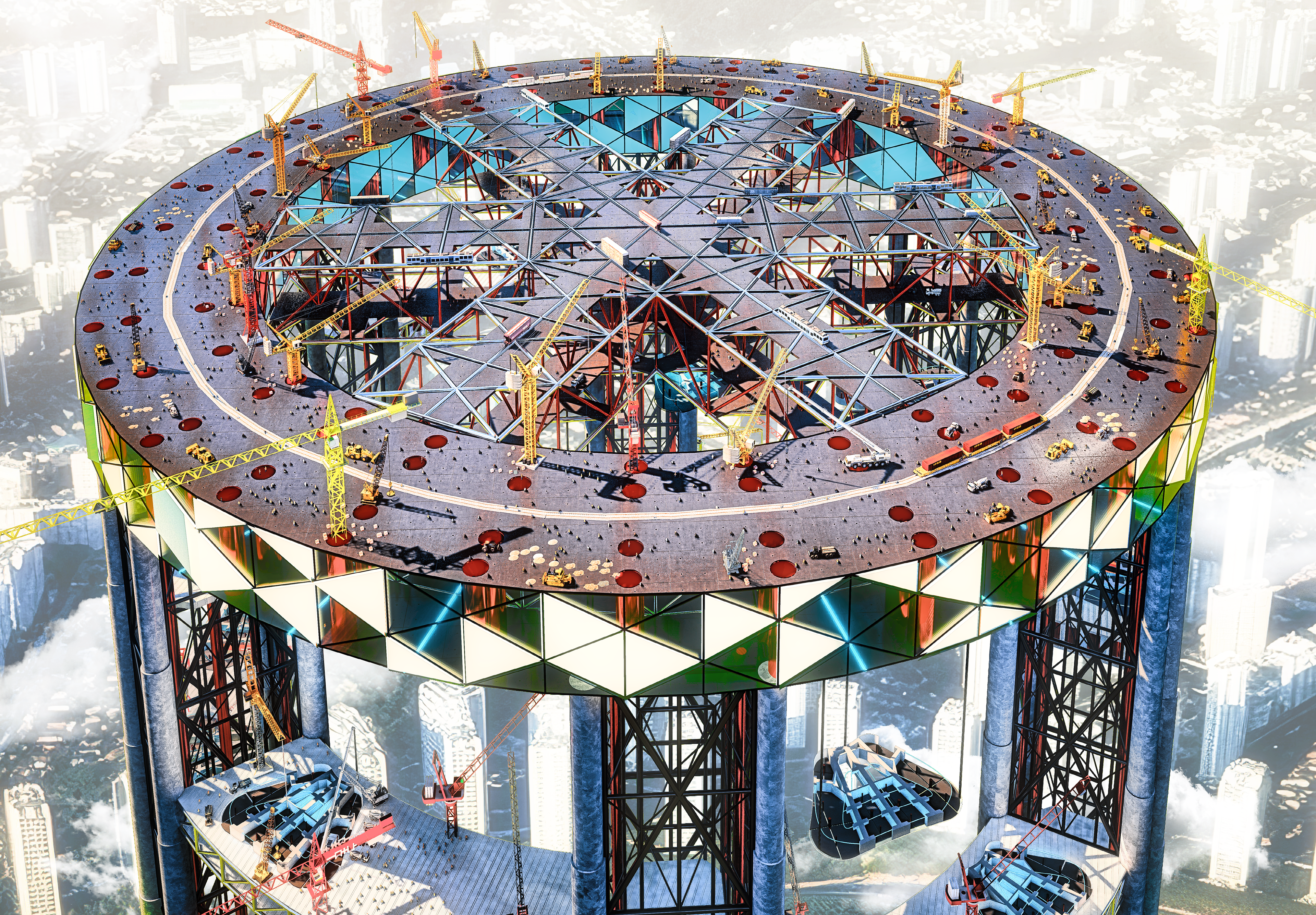
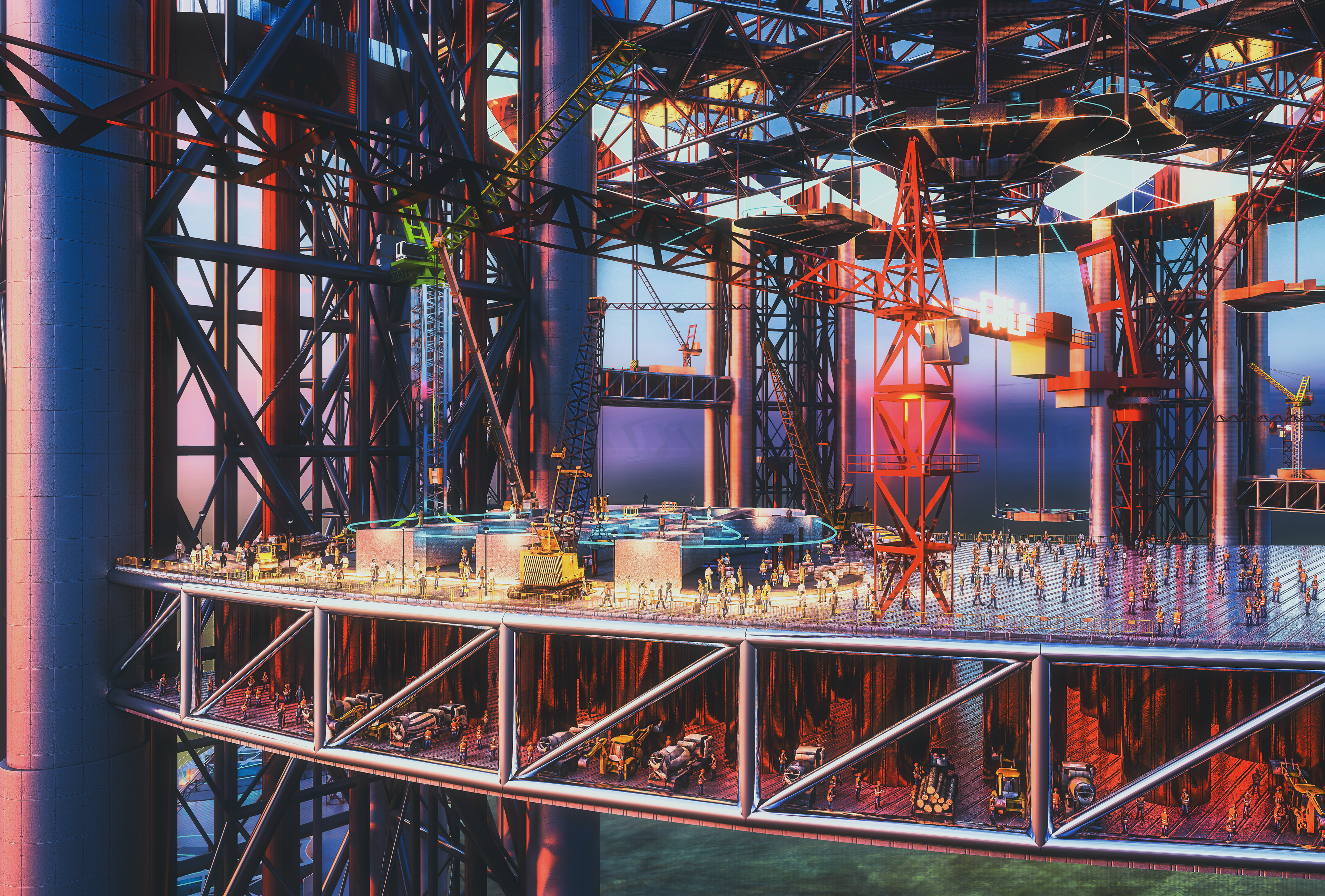
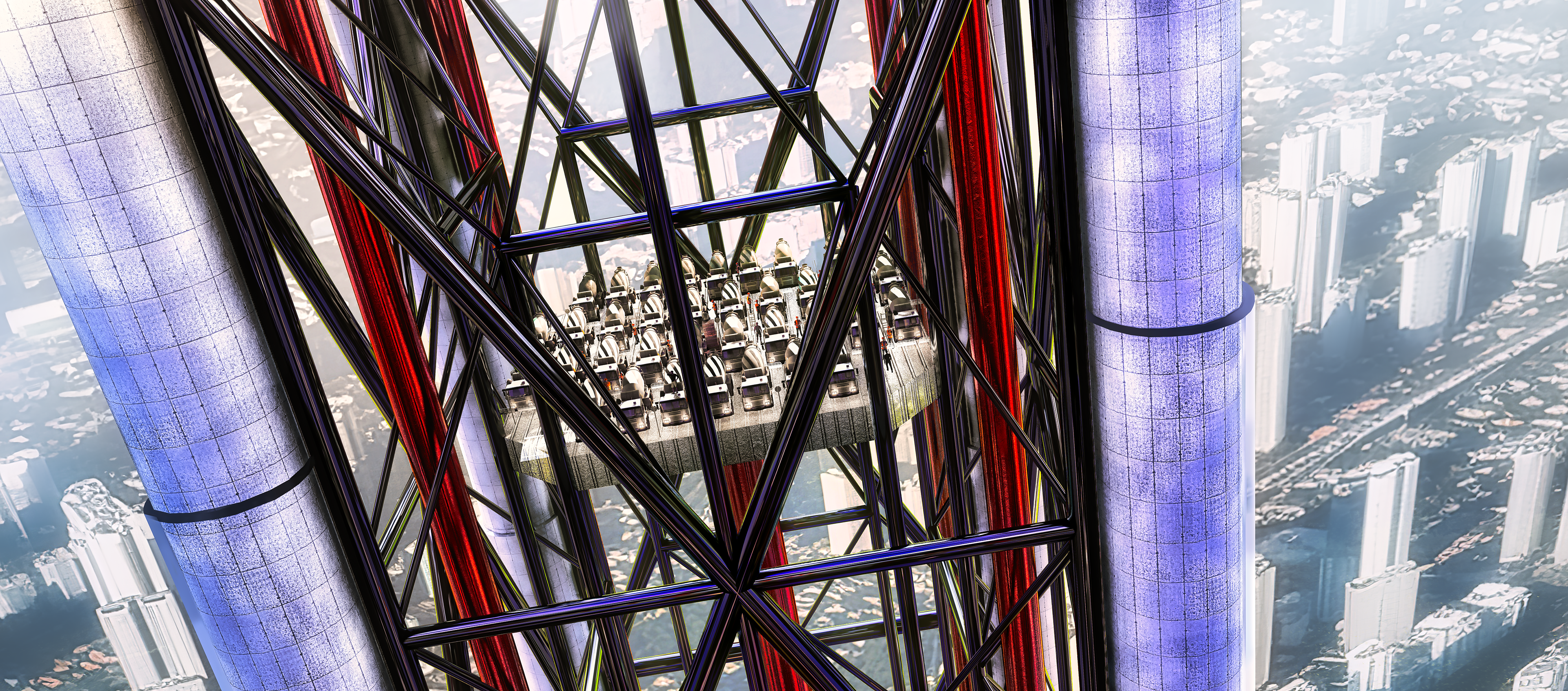
BASE
BASE is a construction base that controls every work in TITAN. From the top, walls, cores, and braces of the tower are installed with in a short period. Trains are operated on the base to efficiently transport various materials, mens, and equipments, and can accomodate about 20,000 builders. The upper boom of the BASE is equipped with cables and rails for moving lifters (modules).
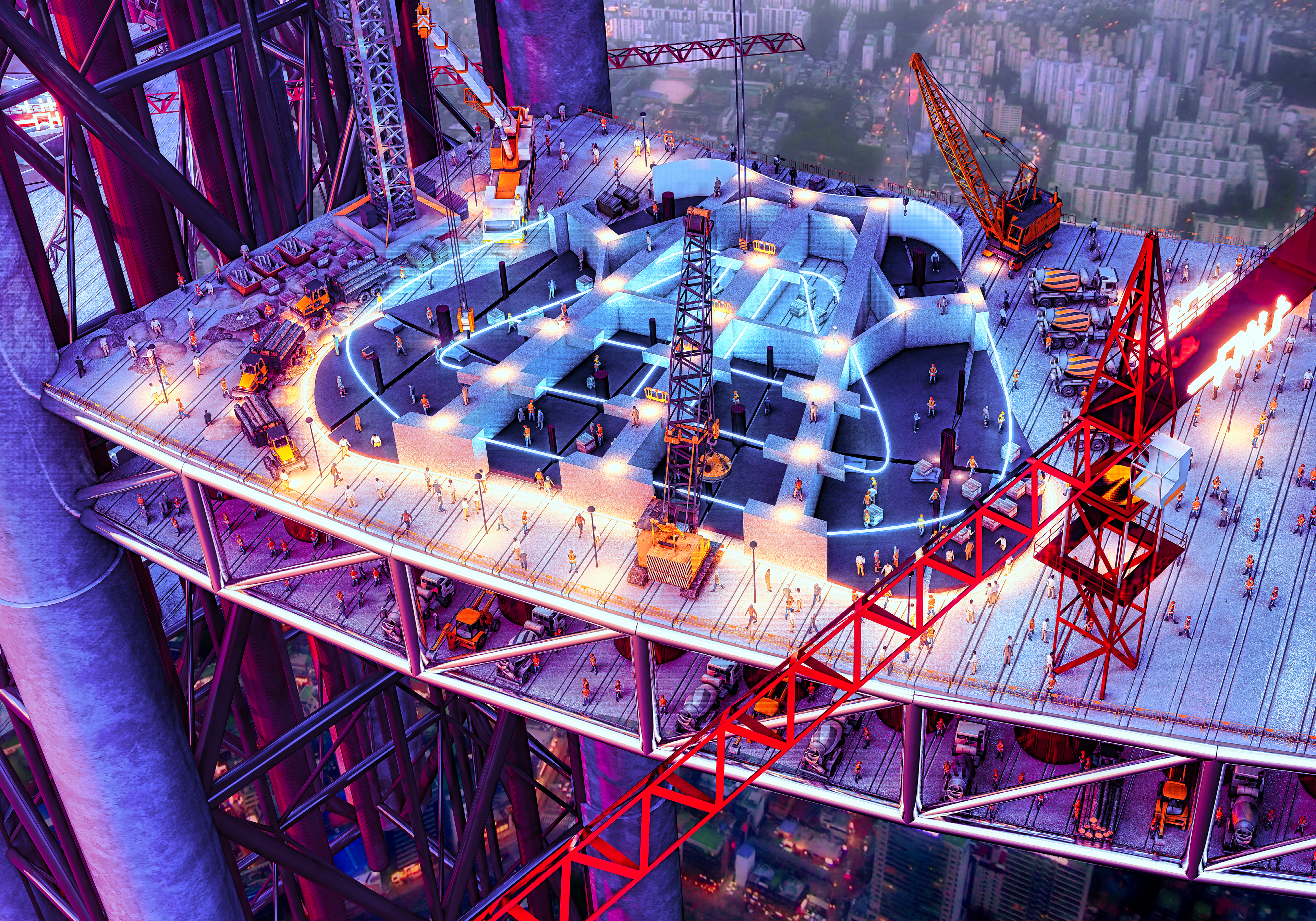
Step 1: MODULE
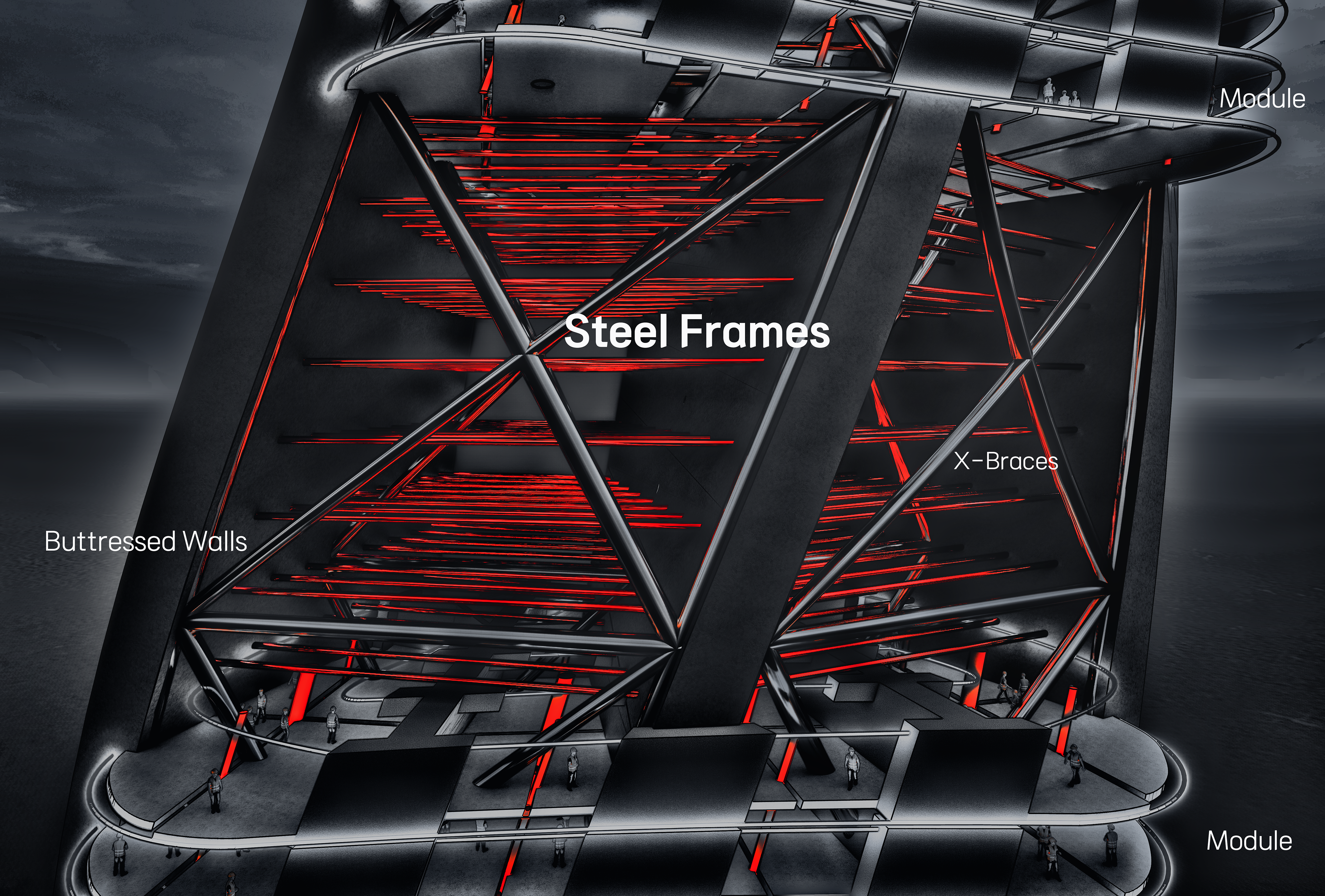
Although the Ascending Dragon has a complex shape, it has a layered module. First, walls in the building are constructed through concrete pouring on the base of TITAN (upper part of TITAN). Second, brace structures are installed between the Buttrressed Walls. Third, modules, which manufactured not to overlap the space they already occupy, are fixed to the wall and the brace structures.
The module is manufactured in six decks between the masts (mega columns) of the TITAN. Up to three modules can be manufactured simultaneously per deck, and the module consists of 1 to 6 floors. Each module is equipped with everything except Buttressed Walls and Braces such as: slabs, columns, internal furniture, pipes, and curtainwalls. It takes an average of two days to manufacture one 2-story module.
Each module has a total of 12 rings on its walls and slab, which can be hoisted with a hook. These rings are installed in a uniform position within the module in consideration of the center of gravity, and the ring is attached to the steel plates (B-Core slab) of module.
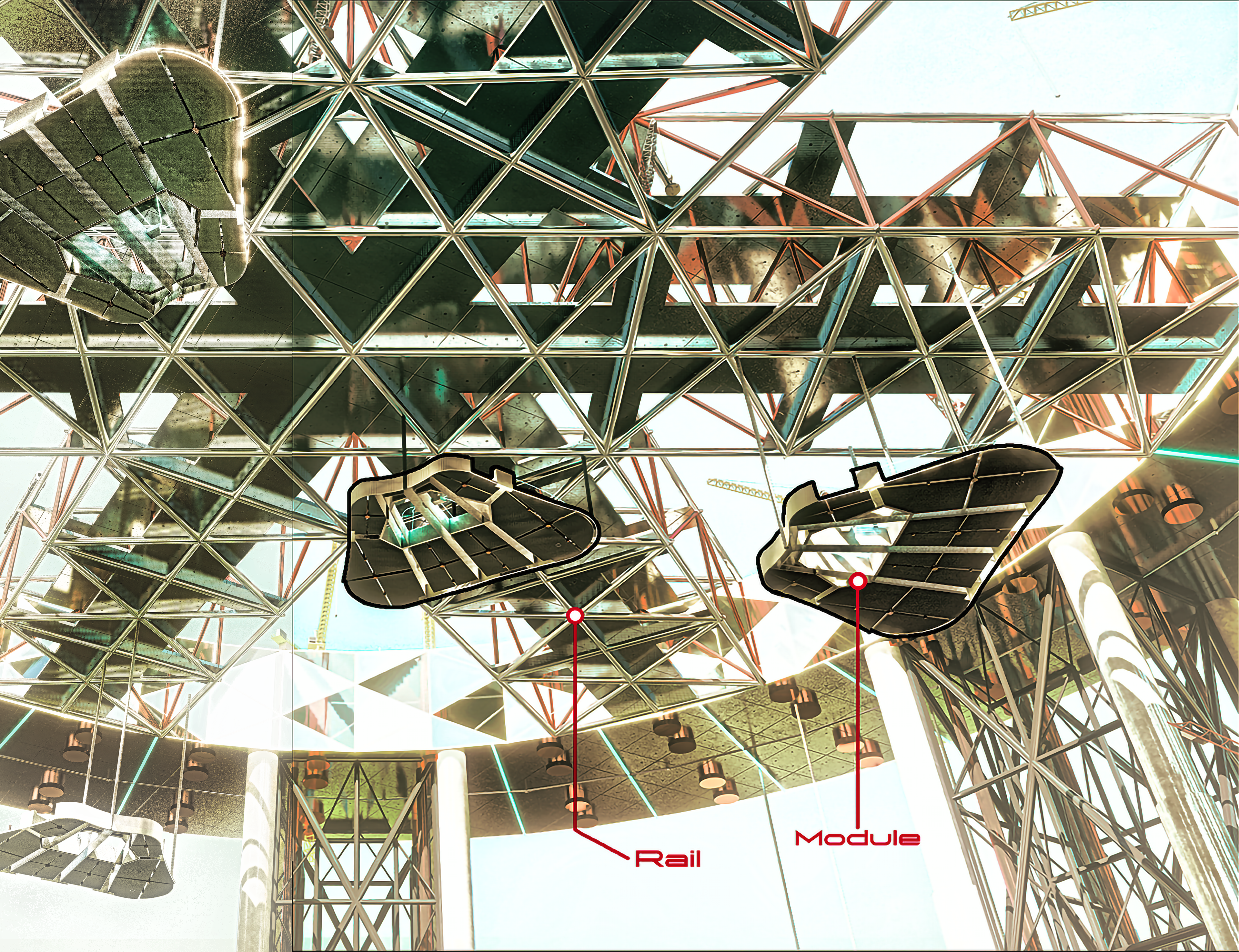
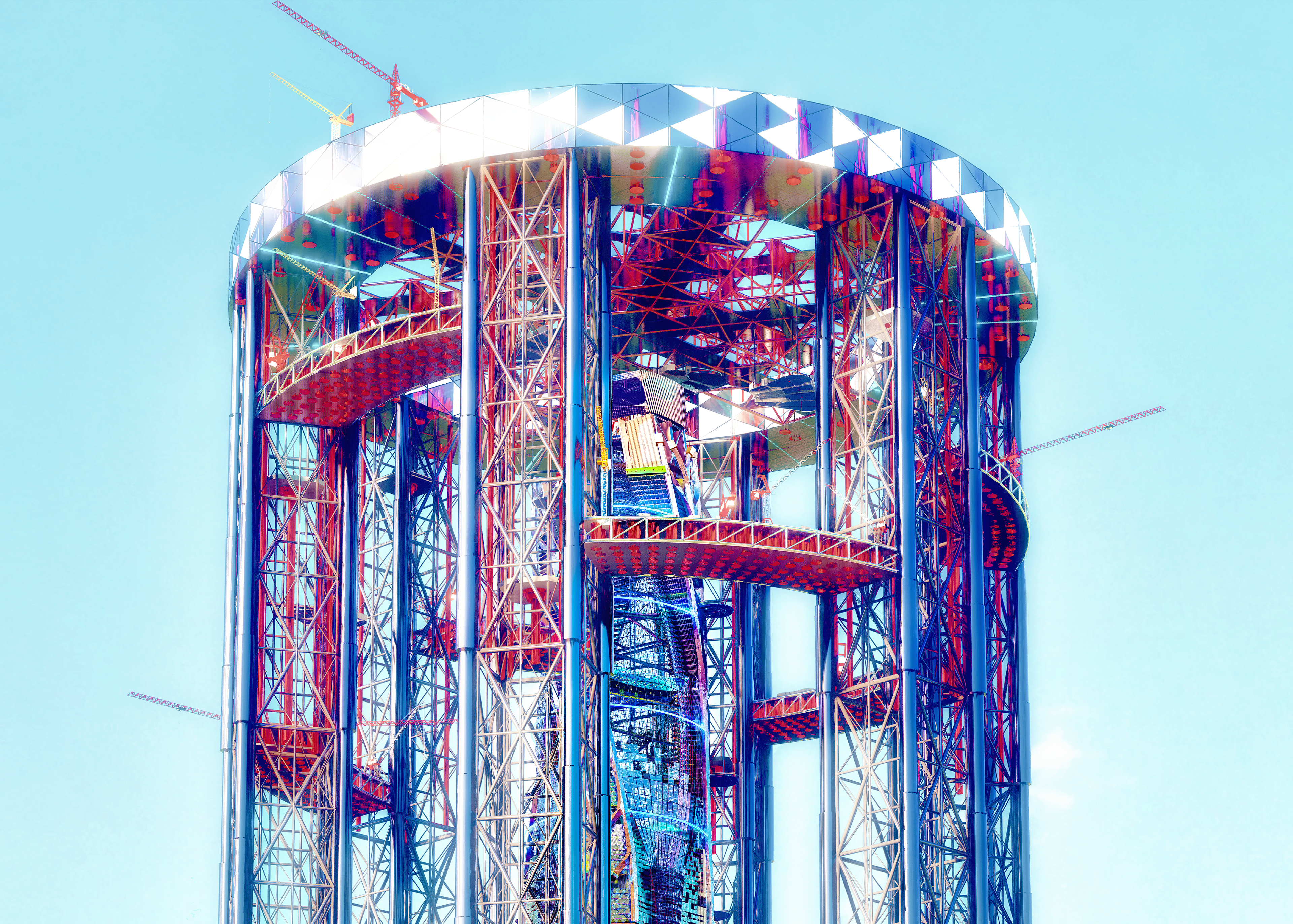
Step 2: Lift & Orientate
A construction base exists on the upper part of TITAN. There are dozens of pulleys and cables in the base, and there are six crane-booms at the inner part of the base. The booms have huge truss structures and rails on which cables can be moved and be followed.
Once the module is manufactured, the base's cables come down to the 12 rings, which are installed on the module, and connects them with hook. After that, the cables are raised by pulleys and moves along the rails of the inner booms.
However, since the design of the building is very complex and irregular, a sophisticated construction process is required. However, the booms and base do not move, but the entire TITAN can rotate by itself. TITAN's mat is annular, connected to the ROOT, and is made of concrete with a thickness of 5 meters. The mat is connected to the Central UFO, so it can be rotated (consistent with the structure of the bicycle wheel). After the construction of the building is finished, TITAN's mat is reorganized into a Resistance Mat and reused as part of the ROOT structure.
Whenever the design of the building rotates, TITAN also rotates together in line with it, so the location and angle of the module can be precisely adjusted.
Step 3: Stacking
Once the manufactured module has been lifted and the angle has been adjusted, the module should be placed in its designated position. The base's pulley is reused when lowering the module, and the module is strongly connected to three butressed walls. The 8 steel frames are connected between each walls, and the module is placed on there. After that, the work of connecting the module and the wall will begin, and a fully equipped floor (with interior, exterior facade, structures, pipes, etc.) will be completed after cleaning up the miscellaneous facilities.
- Anticipation -
Ascending Dragon requires 1352 modules. Assuming that the maximum number of modules that TITAN can produce at the same time is 18, and an average of 9 modules can be produced and stacked per day, the tower can be completed in 150 days (about 5 months). Even if it takes 3 to 4 years including the installation of ROOT and various ground works, it is a great speed of construction.

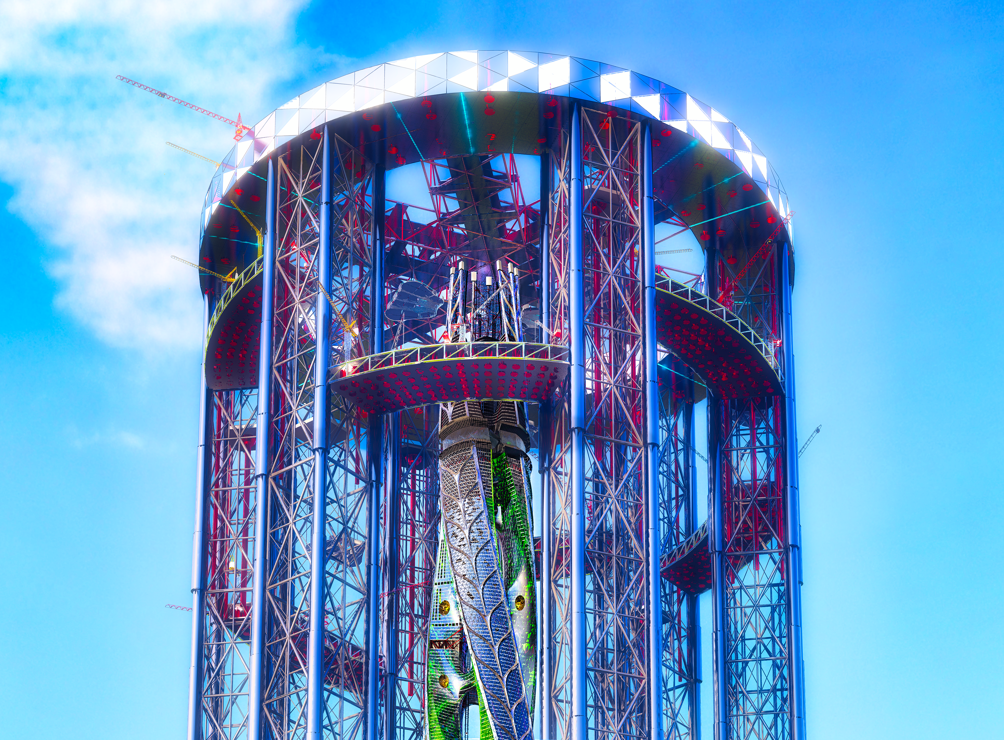


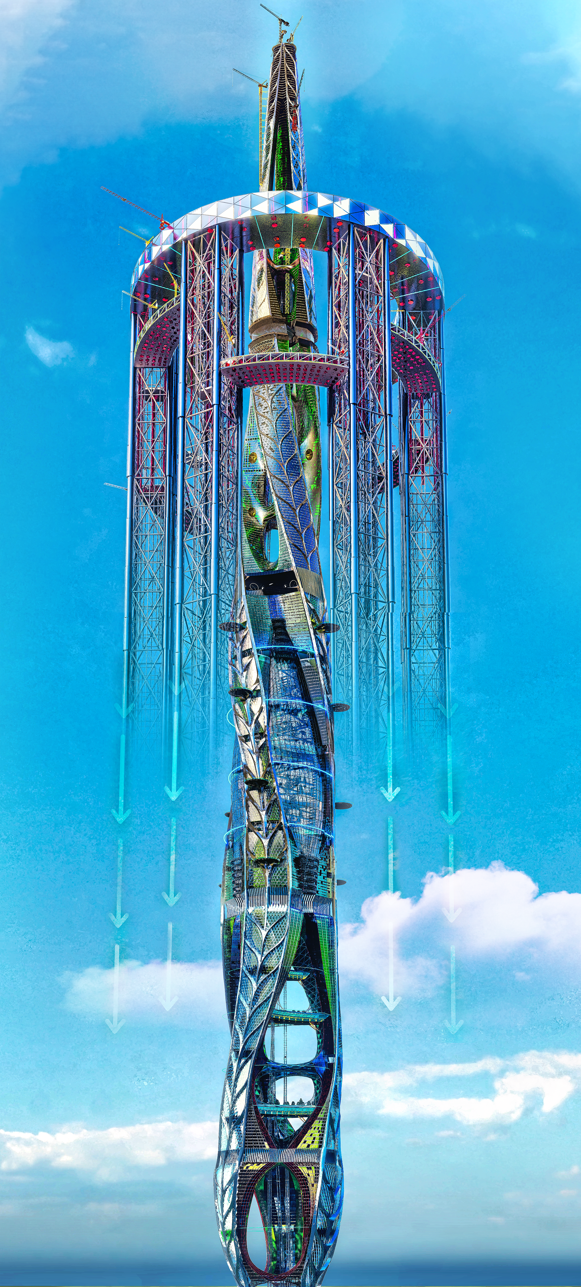
CLIMBING
To stack the modules of the tower, TITAN should always be above the building (except, TITAN only climbs up to 1,500 meters). However, to keep up with the speed of the tower, which has three floors completed in one day, advanced climbing technology is required.
Concept
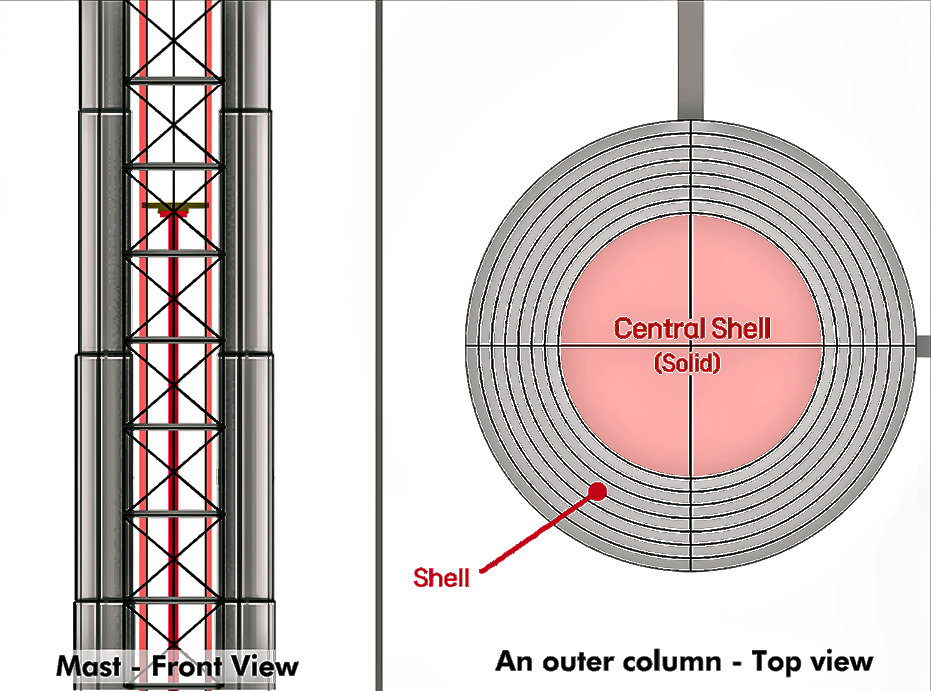
The diagram on the right shows one of the six masts of TITAN. But it seems like the outer columns of the mast is slightly tapered.
It is because the outer columns of each mast consists of eight layers of steel shell, and as the entire structure continues to climb up, every remained shells, except for one shell down below, has rised up. As this process repeated, the outer column's radius will become smaller as it continues to climb up, and finally, TITAN will reach its highest altitude when every shells inside the column has been used.
As the shells rise, concrete is filled inside the shell to support the weight of the upper base, and a large number of brace structures are connected between the columns.
Its climbing process are represented down below specifically.
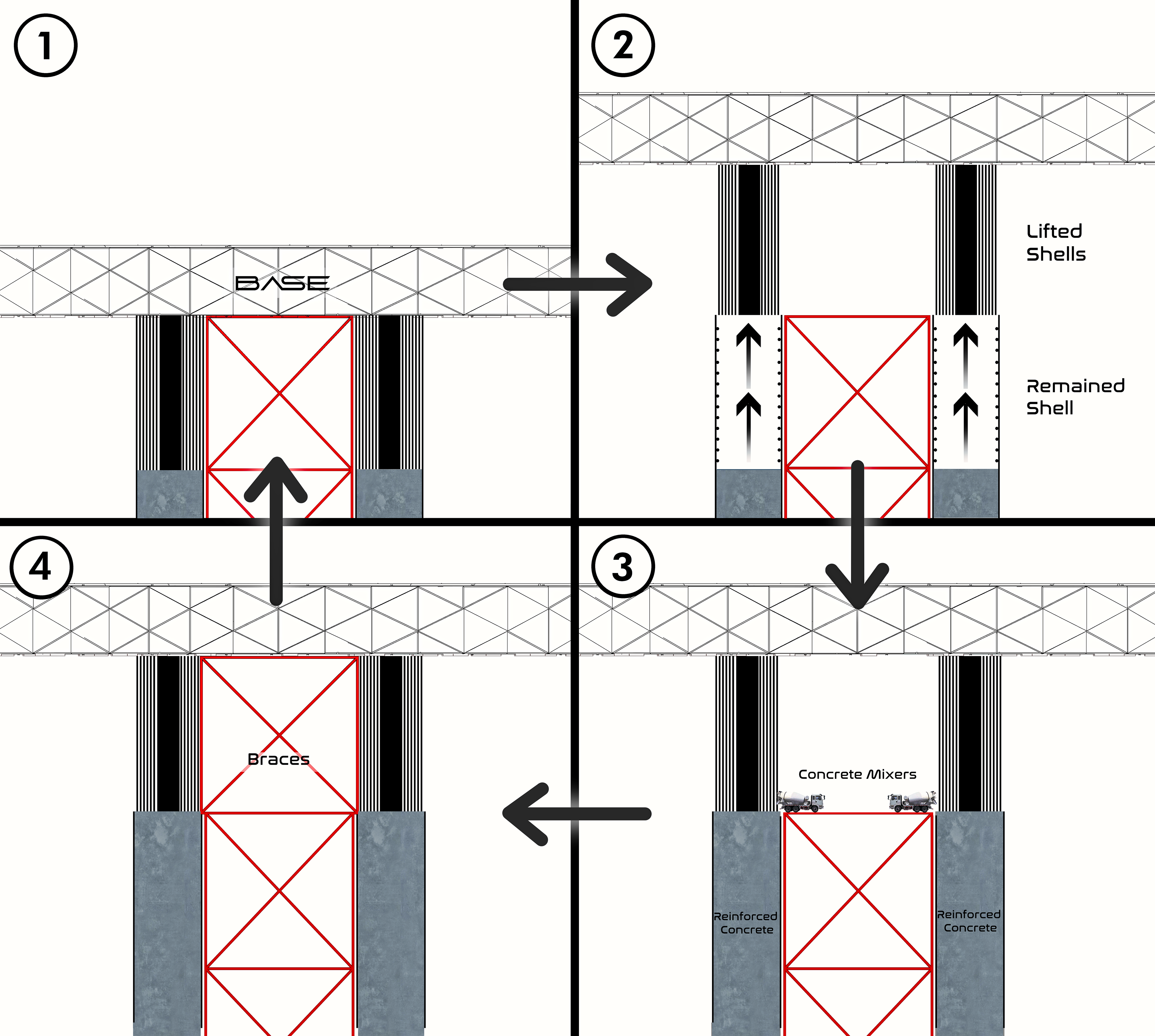
(1)⇒(2)
Except for one of the shells of the existing outer column, the rest of the shells rise through the hydraulic piston. Since the shells rise, the top base rises together.
Except for one of the shells of the existing outer column, the rest of the shells rise through the hydraulic piston. Since the shells rise, the top base rises together.
(2)⇒(3)
Concrete mixer trucks transported by the hoist pour concrete into the void of the remaining shell.
Concrete mixer trucks transported by the hoist pour concrete into the void of the remaining shell.
(3)⇒(4)
Install brace structures to support the base.
Install brace structures to support the base.
(4)⇒(1)
Repeat this whole process until TITAN reaches 1,500 meters.
Repeat this whole process until TITAN reaches 1,500 meters.
DISMANTLING
When the height of the tower reaches 1,500m, TITAN stops rising and is fixed in place. The remaining 450m high part of the tower is built by its own tower crane and jump form as shown in the image above. Concrete is not used at this time, and the tower slab is replaced with a modular slab consisting of stainless steel. Materials and modules required for the upper part construction are prepared on the base of TITAN. Tower cranes installed in the tower lift them up and install them in their designated places.
When the construction of the tower is completed, TITAN is dismantled. At this time, the concrete present inside the outer columns of the masts are liquefied. In the process of liquefying concrete, various chemicals such as phosphoric acid (H3PO4), trisodium phosphate (Na3PO4), and muriatic acid (HCl) are used. Then, liquefied concrete is extracted and the bracing is removed. Through repetition of this process, the height of the stretched outer columns are reduced, the base is lowered, and TITAN is dismantled.
After TITAN is dismantled, the place where the mat was located is remodeled into a Resistance Mat, which is part of the ROOT's structure, and the upper protrusion of the ROOT is covered using gardens and park buildings.